|
Debug: Diagnostics
|
|


|
(Original Document)
|
|
Debug: Diagnostics
|
|
|
(Original Document)
|
|
Element
|
Associated language object
|
Description
|
|---|---|---|
|
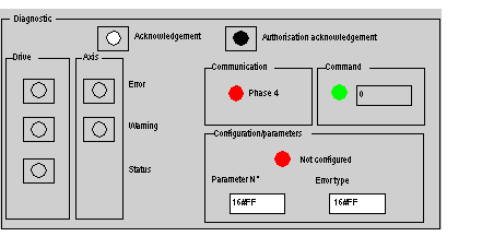
Acknowledgement Button
|
%Qr.m.c.15
|
Fault acknowledgement
|
|
Authorisation acknowledgementbutton
|
%Qr.m.c.31
|
Confirm faults
|
|
Element
|
Description
|
|
|---|---|---|
|
Error LED
Errorbutton
|
(1)
|
|
|
Warning LED
Warning button
|
(1)
|
|
|
Status LED
Status Button
|
(1)
|
|
|
(1): When the LED is on, a left click on the button will open a window displaying the type of fault.
|
||
|
Element
|
Description
|
|
|---|---|---|
|
Error LED
Error Button
|
(1),
Note: The drive fault data is not to be taken into account if there is a SERCOS® communication error.
|
|
|
Warning LED
Warning Button
|
(1)
|
|
|
(1): When the LED is on, a left click on the button will open a window displaying the type of fault.
|
||
|
Element
|
Associated language object
|
Description
|
|---|---|---|
|
Phase 4 LED
|
%Ir.m.c.16
|
|
Element
|
Associated language object
|
Description
|
|---|---|---|
|
LED
|
%MWr.m.c.1:X2
|
Faulty explicit command (Action_CMD).
|
|
Field
|
%MWr.m.c.19
|
Possible values:
0: parameters OK
Otherwise an error code Seewrite_cmd:programming errors command chapter
|
|
Element
|
Associated language object
|
Description
|
|---|---|---|
|
LED Not configured
|
%Ir.m.c.32
|
Channel is configured.
|
|
N° parameter Field
|
%IW2r.m.c.:X0 to X7
|
Indicates the faulty parameter. See faulty registers chapter
|
|
Error type Field
|
%IW2r.m.c.:X8 to X15
|
Indicates the type of error. See...
|
