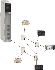
This topic discusses the various components that comprise a Quantum EIO system. Connecting the Quantum to remote I/O devices in a Quantum EIO system is known as the . This topic discusses the 3 types of devices within a remote I/O main ring: a local rack, , and ConneXium extended managed switches, pre-configured as dual-ring switches (). You can connect to the main ring via DRSs, and they also enable to connect to the remote I/O network. The system also allows connection to a via a 140NOC78100 head module on the local rack.
Within the main ring in a Quantum EIO system, a local rack is a Quantum rack containing the controller, a power supply, one 140CRP31200 remote I/O head module, a maximum of 6 communication modules, and appropriate I/O modules. A 140CRP31200 module is not considered a communication module. You can install a maximum of five 140NOC78000 distributed I/O head modules and one 140NOC78100 control head module.
NOTE:
While the 140 NOC 78• 00 head modules are designed specifically for a Quantum EIO system, you can use 140 NOE 771 ••, 140 NOC 771 ••, and 140 NOM 2•2 00 modules to mange Ethernet distributed I/O and/or Modbus Plus systems. These modules may have performance restrictions that the 140 NOC 78• 00 modules do not have in a Quantum EIO system. For example:
-
Only one 140 NOE 771 •• module may participate in the remote I/O network.
-
You cannot connect a 140 NOC 771 •• to a 140CRP31200 head module on the local rack.
-
140 NOC 771 •• modules are supported only in standalone systems; they are not supported in systems.
NOTE: 140 CRP 93• 00 head modules may be installed on the local rack to manage legacy (S908) remote I/O drops. These drops are isolated from the Ethernet remote I/O network.
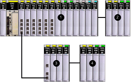
A local rack consists of 1 or 2 racks — the main rack and the extended rack. A main rack is required in the Quantum EIO architecture; an extended rack is optional, and when it is present, it is considered part of the local rack.
The graphic below is an example of a Quantum EIO local rack with an extended rack.
1
main local rack
2
extended local rack
A remote I/O drop is a remote Quantum or Modicon X80 rack of I/O modules (also contains a power supply and a •••CRA312•0 adapter module) that is connected to an Ethernet remote I/O network.
Remote I/O drops are connected to the Ethernet remote I/O network in the following ways:
-
on the main ring — connected via copper cable to the 140CRP31200 head module on the local rack or to another remote I/O drop (which may be connected to another remote I/O drop or the 140CRP31200 head module on the local rack)
-
on a sub-ring — connected via copper cable to a located on the main ring
A remote I/O drop consists of 1 or 2 remote racks — the main rack (containing the •••CRA312•0 adapter module) and an optional extended rack. (The BMXCRA31200 adapter module supports only 1 rack.)
A maximum of 31 remote I/O drops can be supported in a Quantum EIO network.
The graphic below shows a remote I/O drop (with an extended remote rack) connected to a local rack (with an extended local rack):
1
main local rack
2
extended local rack
3
main remote rack
4
extended remote rack
Legacy (S908) Remote I/O Drops:
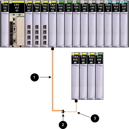
You can install a legacy (S908) Quantum 140 CRP 93• 00 remote I/O head module on the local rack to support legacy (S908) remote I/O drops — 800 series I/O drops, SY/MAX drops, or Quantum remote I/O drops. Legacy (S908) remote I/O drops are not part of a Quantum EIO network.
1
trunk cable
2
trunk terminator
3
drop cable
Dual-Ring Switches (DRSs)
A ConneXium extended managed switch that has been configured to operate on a Quantum EIO network is called a dual-ring switch (). DRS predefined configurations provided by Schneider Electric can be downloaded to a ConneXium extended managed switch to support the special features of the
main ring / sub-ring architecture. A switch with one of these DRS predefined configurations is one of the
4 types of Quantum EIO devices.
A DRS can be used to:
-
enable the use of fiber cable for distances greater than 100 m between 2 contiguous remote devices (You can also use
140 NRP 312 00/01 or
BMX NRP 0200/01 fiber converter modules for this purpose.)
-
enable distributed I/O devices to participate on the remote I/O network
-
enable recovery support for devices and cables on the sub-rings
-
isolate the sub-rings from one another and from the main ring to improve system performance
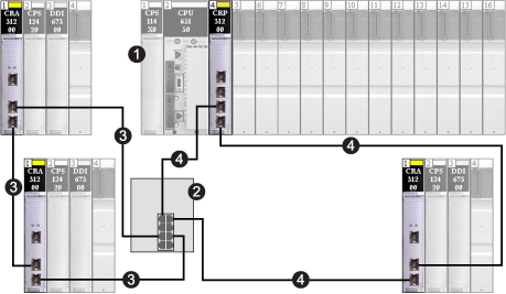
This is a simple view of a DRS connecting a remote I/O sub-ring to the main ring.
1
local rack (including the 140CRP31200 head module)
2
DRS
3
remote I/O sub-ring (connecting remote I/O drops, including 140CRA31200 adapter modules)
4
main ring
Main Ring / Sub-ring Redundant Connections
Use 2 DRSs — one installed with a
master predefined configuration and other installed with a corresponding
slave predefined configuration — to provide a redundant connection between the main ring and the sub-ring. The
master DRS passes data between the main ring and the sub-ring. If the
master DRS becomes inoperable, the
slave DRSs takes control and passes data between the main ring and the sub-ring. For details, refer to the
Predefined Configuration Files chapter.
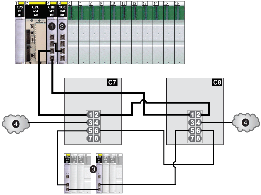
The following illustration is an example of main-ring/sub-ring DRS redundant connections in a Quantum EIO network:
C7
DRS using the C7 predefined configuration file for a master copper remote I/O main ring with a remote I/O sub-ring and distributed I/O clouds
C8
DRS using the C8 predefined configuration file for a slave copper remote I/O main ring with a remote I/O sub-ring and distributed I/O clouds
1
140CRP31200 remote I/O head module on local rack
2
140NOC78000 distributed I/O head module connected to the 140CRP31200 module to support the distributed I/O clouds (4)
3
remote I/O sub-ring (with a 140CRA31200 adapter module on each remote I/O drop)
4
distributed I/O clouds
DRSs are discussed in detail later in this guide.
You can install a
140 NRP 312 00/01 fiber converter module on a Quantum local rack and Quantum Ethernet remote I/O drops to convert copper cable to fiber for distances greater than 100 m. You can also install a
BMX NRP 0200/01 module on X80 remote I/O drops for the same purpose.
NOTE: You cannot use these modules to connect remote I/O or distributed I/O sub-rings to the main ring.
In a Quantum EIO system, can be:
NOTE: Distributed I/O devices can be connected to the Quantum EIO network via DRSs or via the service ports on the 140CRP31200 head module, the 140CRA31200 adapter module, or the BMXCRA31210 adapter module. They cannot be connected directly to the main remote I/O ring.
NOTE: Do not connect a device with a speed in excess of 100 Mbps to the service port. If the device is configured for a speed that exceeds 100 Mbps, the Ethernet link may not be established between the device and the module through the service port.
The maximum load the network can process from distributed I/O devices is:
Example of a Distributed I/O Device:
Shown throughout this documentation is an Advantys STB island. When an STB island is used with an STB NIP 2311 network interface module (NIM), the island can be connected directly to a distributed I/O sub-ring. The STB NIP 2311 NIM has 2 Ethernet ports and it supports RSTP, making it able to operate on a sub-ring.
1
STB NIP 2311 NIM
2
STB PDT 3100 (24 VDC power distribution module)
3
STB DDI 3230 24 VDC (2-channel digital input module)
4
STB DDO 3200 24 VDC (2-channel digital output module)
5
STB DDI 3420 24 VDC (4-channel digital input module)
6
STB DDO 3410 24 VDC (4-channel digital output module)
7
STB DDI 3610 24 VDC (6-channel digital input module)
8
STB DDO 3600 24 VDC (6-channel digital output module)
9
STB AVI 1270 +/-10 VDC (2-channel analog input module)
10
STB AVO 1250 +/-10 VDC (2-channel analog output module)
11
STB XMP 1100 (island bus termination plate)
A distributed I/O cloud is a group of distributed I/O devices that are not required to support . Distributed I/O clouds require only a single (non-ring) copper wire connection. They can be connected to some of the copper ports on DRSs, or they can be connected directly to 140 NOC 78• 00 modules in the local rack. Distributed I/O clouds cannot be connected to sub-rings.
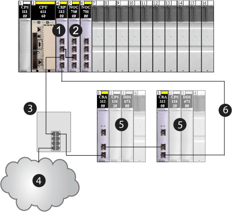
When a distributed I/O cloud is connected to a DIO cloud port on a DRS (or the service ports on the 140CRP31200 remote I/O head module or the •••CRA312•0 remote I/O adapter module) in the main ring, the distributed I/O devices within the cloud are a physical part of the Quantum EIO network.
In this instance, connect the 140CRP31200 head module to a 140NOC78000 head module in the local rack, since the 140NOC78000 module manages the distributed I/O devices.
1
140CRP31200 remote I/O head module
2
140NOC78000 distributed I/O head module
3
DRS
4
distributed I/O cloud
5
remote I/O drop
6
main ring
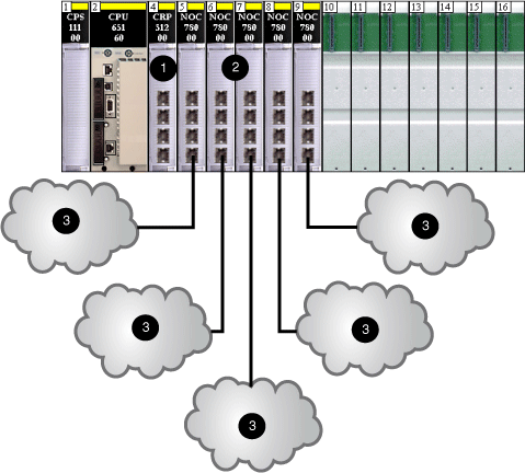
When a distributed I/O cloud is connected directly to a 140 NOC 78• 00 module, the distributed I/O devices are isolated from the remote I/O network if the 140 NOC 78• 00 module is not connected to another head module on the local rack.
1
140CRP31200 remote I/O head module
2
140NOC78000 distributed I/O head modules
3
distributed I/O clouds
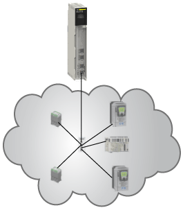
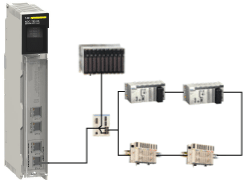
Distributed I/O clouds contain either a single device or several devices designed in
star, mesh, or daisy chain topologies. The example below shows a distributed I/O cloud with daisy-chained devices.
Sub-rings are connected to the main ring via DRSs. There are 2 types of sub-rings — remote I/O sub-rings and distributed I/O sub-rings.
-
Remote I/O sub-rings contain only remote I/O devices, including one •••CRA312•0 adapter module on each remote I/O drop. A maximum of 31 remote I/O drops can be supported in a Quantum EIO network.
-
Distributed I/O sub-rings contain only distributed I/O devices that have 2 Ethernet ports and support RSTP. A maximum of 128 distributed I/O devices can be supported by all distributed I/O sub-rings.
NOTE: You cannot combine remote I/O devices and distributed I/O devices in the same sub-ring.
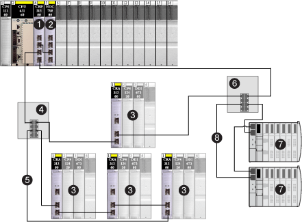
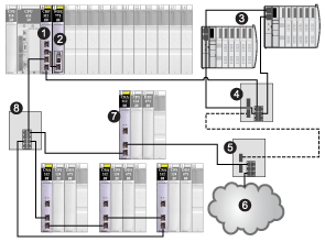
The graphic below shows a remote I/O sub-ring (5) and a distributed I/O sub-ring (8).
1
140CRP31200 remote I/O head module
2
140NOC78000 distributed I/O head module
3
remote I/O drop
4
DRS connected to remote I/O sub-ring
5
remote I/O sub-ring
6
DRS connected to distributed I/O sub-ring
7
distributed I/O devices (STB NIP 2311 NIM on an STB island)
8
distributed I/O sub-ring
Copper and fiber cable types and maximum distances for remote I/O devices are discussed in the cable installation topic in the respective Quantum Ethernet I/O head module user guide.
Calculating Maximum Devices for a Remote I/O Network
The main ring in a Quantum EIO system supports up to 32 devices. The 4 types of valid devices are:
-
a
local rack (containing communication modules, remote I/O modules and distributed devices)
-
a maximum of 31
remote I/O drops (each drop containing a •••CRA312•0 adapter module)
-
DRSs, each of which should be counted as 2 devices when you are doing your main ring capacity calculations
Remote I/O Network Topologies
In a Quantum EIO system, remote I/O devices are connected in a daisy chain loop topology. The remote I/O network utilizes the following 2 types of loop topologies:
|
Topology Type
|
Definition
|
Example
|
|
simple daisy chain loop
|
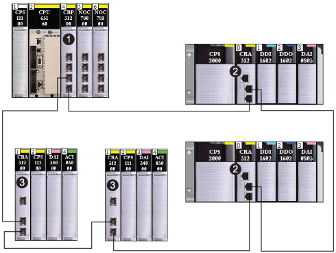
A simple daisy chain loop consists of a local rack (containing a 140CRP31200 head module), and one or more Quantum or Modicon X80 remote I/O drops (each drop containing a •••CRA312•0 adapter module). No sub-rings are allowed.
|
1 140CRP31200 remote I/O head module on the local rack
2 BMXCRA312•0 adapter module on a Modicon X80 Ethernet remote I/O drop
3 140CRA31200 adapter module on a Quantum Ethernet remote I/O drop
|
|
high-capacity daisy chain loop
|
A high-capacity daisy chain loop uses to connect sub-rings (remote I/O or distributed I/O) and/or distributed I/O clouds to the remote I/O network.
|
1 140CRP31200 remote I/O head module on the local rack
2 140NOC78000 distributed I/O head module (connected to the 140CRP31200 module to manage the STB distributed I/O sub-ring)
3 STB distributed I/O sub-ring
4 DRS (connected to an STB distributed I/O sub-ring)
5 DRS (connected to a distributed I/O cloud)
6 distributed I/O cloud (managed by the 140NOC78000 module in the local rack)
7 remote I/O drop (including a 140CRA31200 adapter module) on the main ring
8 DRS (connected to a remote I/O sub-ring)
|
Remote I/O Main and Sub-Ring Design Examples
Given the considerations set forth above, with respect to remote I/O main and sub-rings, you could construct a Quantum EIO network in the following designs, to deploy the maximum number of remote I/O devices.
Design 1:
-
a main ring with:
-
no remote I/O sub-rings
Design 2:
-
a main ring with:
-
1 – 140CRP31200 head module
-
11 – •••CRA312•0 adapter modules in remote I/O drops
-
5 – DRSs, each supporting a remote I/O sub-ring (each sub-ring supporting two •••CRA312•0 adapter modules in remote I/O drops
Distributed I/O Network Topologies
|
Topology Type
|
Definition
|
Example
|
|
star
|
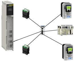
In a star topology, all single-port Ethernet devices are connected through an intermediate device, such as a .
|
|
|
ring (loop)
|
In a ring topology (also known as a daisy chain loop), dual-port Ethernet devices that support are connected in a ring. With a ring topology, network redundancy is achieved. A is required in this topology.
NOTE: Single-port Ethernet devices can connect to the Quantum EIO network via a DRS, but they are not part of the ring.
|
|
|
mesh
|
In a mesh topology, single-port Ethernet devices are connected to each other through intermediate devices, such as a ConneXium extended managed switch (not required to be configured as a DRS). With a mesh topology, network redundancy is possible.
|
|
A device network is an Ethernet remote I/O network where distributed I/O devices can participate with remote I/O devices.
In this type of network, remote I/O traffic has the highest priority on the network, so it is delivered ahead of distributed I/O traffic, providing remote I/O exchanges.
The device network contains a local rack, remote I/O drops, distributed I/O devices, DRSs, adapter class devices, etc. Devices connected to this network follow certain rules to provide remote I/O . Details about determinism are discussed in the
Application Response Time chapter.
A control network is an Ethernet-based network containing PLCs, SCADA systems, an NTP server, PCs, AMS system, switches, etc. Two kinds of topologies are supported:
-
flat — All the devices in this network belong to same subnet.
-
2 levels — The network is split into an operation network and an inter-controller network. These 2 networks can be physically independent, but are generally linked by a routing device.
The 140NOC78100 control head module is installed on the local rack of a Quantum EIO system. The module provides the interfaces to communicate with a control network and client applications on an Ethernet remote I/O network.
The main purpose of the 140NOC78100 module is to provide transparency between the control network, the device network, and an extended distributed I/O network, while preserving device network determinism. In addition, the 140NOC78100 module also provides services to communicate with PLC applications running on the control network.
Only one 140NOC78100 module can be configured on the local rack. To communicate with remote I/O devices on a remote I/O network, connect the 140NOC78100 module to the interlink port of the 140CRP31200 remote I/O head module (or a 140NOC78000 distributed I/O head module that is connected to the interlink port of the 140CRP31200 module) on the local rack.
-
To communicate with remote I/O or distributed I/O devices on the device network, connect the 140NOC78100 module to the interlink port of 140NOC78000 module or the 140CRP31200 module.
-
To communicate with devices on an extended distributed I/O network, connect the interlink port of the 140NOC78000 module to the extended port of the 140NOC78100 module.

