This topic presents basic features available in the Quantum EIO system, including software configuration, services, and features that you may already use in your existing system.
Unity Pro software, V7.0 or later, is one software used in a Quantum EIO system.
NOTE: Unity Pro is the former name of Control Expert for version 13.1 or earlier.
For detailed Control Expert configuration procedures, refer to the respective Quantum EIO Installation and Configuration Guide.
The function allows I/O configuration changes in the Ethernet remote I/O drops when the PLC is in RUN mode.
Detailed information is available in the Change Configuration on the Fly User Guide.
-
For Quantum Ethernet remote I/O drops, time stamping is managed by a 140 ERT 854 20 module installed on the local rack or the Ethernet remote I/O drop, with a resolution of 1 ms.
-
For Modicon X80 Ethernet remote I/O drops, time stamping is managed by a BMX ERT 1604 module installed on the Ethernet remote I/O drop, with a resolution of 1 ms. The BMXCRA31210 adapter module time stamps discrete inputs and outputs with a resolution of 10 ms.
Quantum EIO modules communicate using the following parameters, which can be configured with Unity Pro 7.0 or later.
-
(See the configuration topic in the respective Quantum EIO Installation and Configuration Guide.)
NOTE: The •••CRA312•0 adapter modules automatically receive an IP address. We recommend that you do not change this IP address.
-
(See the configuration topic in the respective Quantum EIO Installation and Configuration Guide.)
-
(See the configuration topic in the respective Quantum EIO Installation and Configuration Guide.)
-
(See the configuration topic in the respective Quantum EIO Installation and Configuration Guide.)
-
(See the configuration topic in the Quantum EIO Remote I/O Modules Installation and Configuration User Guide, the Quantum Ethernet I/O Distributed I/O Network Installation and Configuration User Guide, or the Quantum EIO Control Network Installation and Configuration User Guide.)
-
(See the configuration topic in the Quantum EIO Control Network Installation and Configuration User Guide.)
-
IP forwarding service (See the configuration topic in the Quantum EIO Control Network Installation and Configuration User Guide.)
Quantum EIO Ethernet communication modules support explicit messaging via and Modbus TCP protocols. This feature is detailed in the respective Quantum EIO Installation and Configuration Guide.
-
EtherNet/IP explicit messaging using the MBP_MSTR function block
-
Modbus TCP explicit messaging using the MBP_MSTR function block
-
explicit messaging via the Control Expert graphic user interface GUI
A Quantum EIO system offers high availability solutions, using configuration.
The minimum Quantum Hot Standby system does not require any
remote I/O drops (that include •••CRA312•0 adapter modules), but it requires at least 1 (and only 1) 140CRP31200 head module on both primary and secondary
local racks.
Just as in a standalone system, can be used in a Hot Standby system to:
A DRS predefined configuration, CRPLinkHotStandbyLDVxx.cfg, is available for Hot Standby systems that enables you to separate the primary and standby PLCs by a long distance using fiber optic cable.
NOTE: You can also use a 140 NRP 312 00/01 fiber converter module to convert copper cable to fiber cable for distances greater than 100 m. For more details, refer to the
fiber converter module topic.
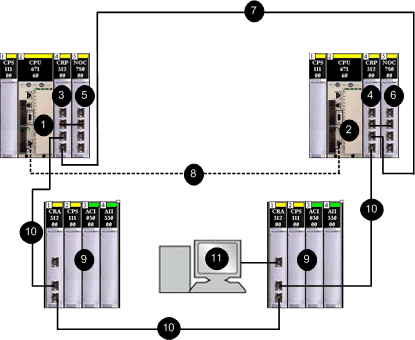
The following figure shows a simple daisy chain loop architecture of a Quantum EIO Hot Standby system. Refer to the Quantum Hot Standby System User Manual for details on setting up and maintaining the system as well as the features available.
1
primary CPU controller
2
standby CPU controller
3
primary 140CRP31200 remote I/O head module
4
standby 140CRP31200 module
5
primary 140NOC78000 distributed I/O head module (interlinked with the 140CRP31200 module
6
standby 140NOC78000 head module (interlinked with the 140CRP31200 module
7
copper connection between primary and standby head modules
8
CPU-sync fiber link
9
Ethernet remote I/O drops (with 140CRA31200 adapter modules)
10
Ethernet cables in daisy chain loop (main ring)
11
Control Expert connection using the service port on the 140CRA31200 adapter module (NOTE: Interlink the 140CRP31200 module and the 140NOC78000 module on the local rack to allow the Control Expert connection.)
Redundancy on Main Ring / Sub-ring Connections
Two DRSs can be used to provide a redundant connection between the main ring and the sub-ring. One DRS is installed with a master predefined configuration, and the other is installed with a corresponding slave predefined configuration. The master DRS passes data between the main ring and the sub-ring. If the master DRS becomes inoperable, the slave DRS takes control and passes data between the main ring and the sub-ring. For details, refer to the Predefined Configuration Files chapter.
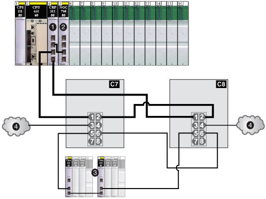
The example below shows 2 DRSs creating a redundant connection between the main ring and the remote I/O sub-ring.
C7
a DRS using the C7 predefined configuration file for a master copper remote I/O main ring with a remote I/O sub-ring and distributed I/O clouds
C8
a DRS using the C8 predefined configuration file for a slave copper remote I/O main ring with a remote I/O sub-ring and distributed I/O clouds
1
a 140CRP31200 remote I/O head module on the local rack
2
a 140NOC78000 distributed I/O head module interlinked with the 140CRP31200 module
3
a remote I/O sub-ring
4
distributed I/O clouds 
