|
|
Original instructions
|
|
NOTICE
|
|
UNINTENDED EQUIPMENT OPERATION
When installing modules with fiber optic transceivers, do the following to help prevent dust and pollution from disrupting light production into the fiber optic cable.
Failure to follow these instructions can result in equipment damage.
|
|
BMX NRP 0200
|
BMX NRP 0201
|
140 NRP 312 00
|
140 NRP 312 01
|
|
|---|---|---|---|---|
|
rack/drop type
|
X80
|
X80
|
Quantum
|
Quantum
|
|
fiber type
|
multi-mode
|
single-mode
|
multi-mode
|
single-mode
|
|
||||

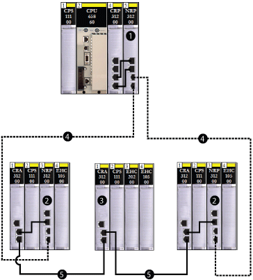
1140CRP31200 remote I/O head module on the local rack connected via copper cable to a transceiver port of a 140 NRP 312 00/01 fiber converter module
2Quantum remote I/O drop connected to the main ring via fiber and copper cable. (A 140 NRP 312 00/01 module connects the drop to the main ring via fiber, and the 140 CRA 312 00 adapter module connects the drop to the main ring via copper.)
3Quantum remote I/O drop connected to the main ring via copper cable
4(- - - - ) fiber portion of the main ring
5( —— ) copper portion of the main ring

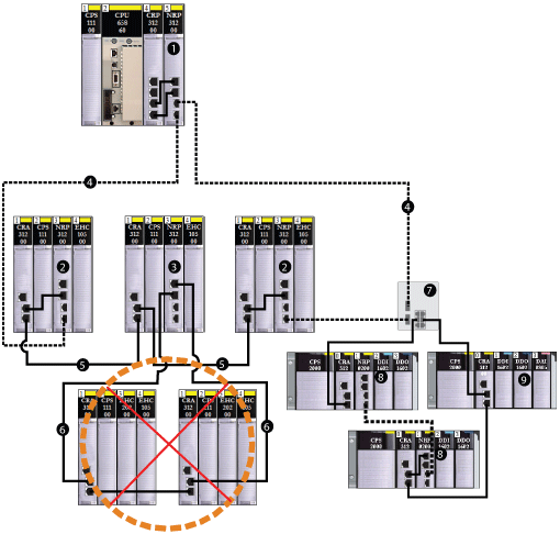
1140 NRP 312 00/01 fiber converter module on the local rack
2Quantum remote I/O drop connected to the main ring via copper and fiber cable (A 140 CRA 312 00 adapter module connects the drop via copper cable, and a 140 NRP 312 00/01 module connects the drop via fiber cable.)
3Quantum remote I/O drop connected to the main ring via copper cable, using a 140 CRA 312 00 module
4(- - - - ) fiber cable used for distances greater than 100 m
5( —— ) copper cable used for distances less than 100 m
6Quantum remote I/O sub-ring incorrectly connected to the main ring via copper cable, using a 140 NRP 312 00/01 module
7dual-ring switch (DRS) connecting the X80 sub-ring to the main ring
8X80 drop with a BMX NRP 0200/01 fiber converter module connected to the sub-ring via copper and fiber cable
9X80 drop without a BMX NRP 0200/01 module connected to the sub-ring via copper cable only
|
Step
|
Action
|
|---|---|
|
1
|
|
|
2
|
To connect a fiber converter module to the 140CRP31200 remote I/O head module on the local rack, install a 140 NRP 312 00/01 module and connect to the head module using copper cable.
|
|
3
|
To install a fiber converter module on a remote I/O drop:
|
|
4
|
Connect the 140 NRP 312 00/01 module on the Quantum local rack to a 140 NRP 312 00/01 module on a remote I/O drop on the main ring. The fiber converter modules use small form-factor plugs (SFPs) (transceivers) for the fiber ports. Choose single-mode or multi-mode SFPs.
|
|
5
|
To extend the fiber cable on the main ring to other remote I/O drops on the main ring, repeat steps 3 and 4.
|
|
6
|
To convert the fiber cable to copper cable on the main ring, connect the •••CRA312•0 adapter module on the last remote I/O drop that is connected to the main ring via fiber cable to a •••CRA312•0 adapter module on the next remote I/O drop.
|
|
7
|
To close the main ring, connect the •••CRA312•0 adapter module on the last remote I/O drop that is connected to the main ring via copper cable to the 140CRP31200 module on the local rack.
|

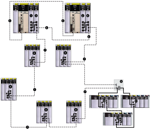
- - - -fiber cable
——copper cable
1140CRP31200 remote I/O head module on the primary Hot Standby PLC connected to a copper port of a 140 NRP 312 00/01 fiber converter module
2140CRP31200 remote I/O head module on the secondary Hot Standby PLC connected to a copper port of a 140 NRP 312 00/01 fiber converter module
3140 NRP 312 00/01 module on the primary Hot Standby local rack
4140 NRP 312 00/01 module on the standby Hot Standby local rack
5fiber cable used for the CPU-sync link
6fiber cable connected to the fiber ports of the 140 NRP 312 00/01 modules to extend the distance between the Hot Standby PLCs beyond 100 m
7fiber cable main ring connecting Quantum Ethernet remote I/O drops to extend the distance beyond 100 m
8Quantum Ethernet remote I/O drop
9dual-ring switch (DRS) connecting the X80 sub-ring to the main ring
10X80 drop with a BMX NRP 0200/01 fiber converter module connected to the sub-ring via copper and fiber cable
11X80 drop without a BMX NRP 0200/01 module connected to the sub-ring via copper cable only
|
Step
|
Action
|
|---|---|
|
1
|
Install a 140 NRP 312 00/01 fiber converter module on both Quantum Hot Standby local racks.
|
|
2
|
Connect the fiber transceiver ports of the 140 NRP 312 00/01 modules on both racks to each other, using fiber cable.
|
|
3
|
Connect the copper port of the 140 NRP 312 00/01 module to the 140CRP31200 remote I/O head module on both local racks, using copper cable.
|