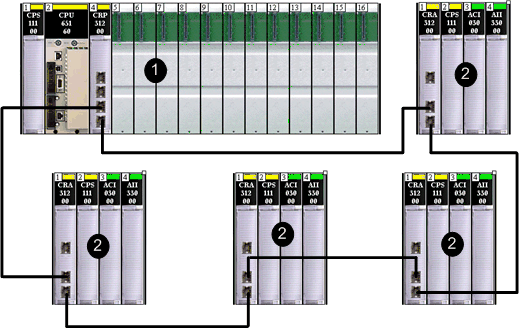
This topic describes planning a simple daisy chain loop network within a Quantum EIO system. A simple daisy chain loop contains the and one or more .
Choose to implement a simple daisy chain loop network if only Ethernet remote I/O drops are included in the loop. No are allowed in the loop. The maximum number of devices in the loop is 32, including the 140CRP31200 remote I/O head module in the local rack.
NOTE: You cannot attach sub-rings (either remote I/O or distributed I/O) to the in a simple daisy chain loop network.
ConneXium extended dual-ring switches () are not required in a simple daisy chain loop configuration.
The daisy chain loop is the least complex network configuration in a Quantum EIO system. The following graphic shows a 140CRP31200 module in the local rack and Ethernet remote I/O drops looped in an Ethernet remote I/O ring.
1
140CRP31200 remote I/O head module on the local rack
2
BMXCRA312•0 adapter module on an M340 remote I/O drop
3
140CRA31200 adapter module on a Quantum remote I/O drop
NOTE:
-
You need only 1 local rack (containing a 140CRP31200 module). You can also add a maximum of 6 communication modules. Only one of these modules can be a 140NOC78100 control head module.
-
A maximum of 32 devices can be supported, including the local rack.
-
Only copper cable can be used, so there is a maximum distance of 100 m between any 2 consecutive remote I/O devices on the main ring. If you want to extend the distance beyond 100 m, use
DRSs or
140 NRP 312 00/01 or
BMX NRP 0200/01 fiber converter modules to convert the copper cable to fiber.
-
If you connect a distributed I/O cloud to a 140NOC78•00 module on the local rack, the 140NOC78•00 module is not interlinked with the 140CRP31200 module. The distributed I/O cloud is isolated from — that is, it is not physically part of — the remote I/O network.
Planning a Simple Daisy Chain Loop
Follow the steps below to plan a simple daisy chain loop network. Configuration procedures are discussed in the Quantum EIO Remote I/O Modules Installation and Configuration Guide.
|
Step
|
Action
|
|
1
|
Plan the local rack (including the Quantum controller, the power supply module, and the 140CRP31200 remote I/O head module).
|
|
2
|
Plan the Ethernet remote I/O drops. (Each drop includes a •••CRA312•0 adapter module.).
|
NOTE:
-
Connect each Ethernet port marked
Device Network on the 140CRP31200 remote I/O head module (on the local rack) to an Ethernet port on a •••CRA312•0 adapter module (on a remote I/O drop).
-
Connect each Ethernet port marked Device Network on a •••CRA312•0 adapter module to an Ethernet port on another •••CRA312•0 adapter module or to an Ethernet port on the 140CRP31200 head module.
-
The 140CRP31200 head module and the •••CRA312•0 adapter module do not have any fiber ports. Therefore, the maximum distance to another Ethernet remote I/O drop is less than 100 m, using shielded twisted 4-pair CAT5e or greater (10/100 Mbps) cable. (We do not recommend using twisted 2-pair CAT5e or CAT6 cables.) If you want to extend the distance beyond 100 m, use
DRSs or
140 NRP 312 00/01 /
BMX NRP 0200/01 fiber converter modules to convert the copper cable to fiber.
-
The Ethernet ports are clearly labelled on both the 140CRP31200 head module and the •••CRA312•0 adapter module. If you connect these modules to the wrong ports, system performance will be affected.
Planning a Hot Standby System
A Quantum EIO system offers high availability solutions, using configuration.
The minimum Quantum Hot Standby system does not require any remote I/O drops (that include •••CRA312•0 adapter modules), but it requires one 140CRP31200 remote I/O head module on both primary and secondary local racks.
A maximum of 32 devices — two 140CRP31200 head modules on both primary and secondary local racks and 30 remote I/O drops — are allowed in a Hot Standby system.
Refer to the Quantum Hot Standby System User Manual for details on setting up and maintaining the system as well the features available.
