This topic describes planning a high-capacity daisy chain loop within a Quantum EIO system.
A high-capacity daisy chain loop incorporates the use of (with predefined configurations loaded in the switches) in the . The following capabilities are possible with a DRS:
Planning a High-Capacity Daisy Chain Loop
The contains a 140CRP31200 remote I/O head module. If you are connecting to the remote I/O network, interlink the 140CRP31200 remote I/O head module with a 140NOC78000 distributed I/O head module.
NOTE:
-
A Quantum local rack supports a maximum of 6 communication modules. While the 140NOC78•00 head modules are designed specifically for a Quantum EIO system, you can use 140 NOE 771 ••, 140 NOC 771 ••, and 140 NOM 2•2 00 modules to manage Ethernet distributed I/O and/or Modbus Plus systems.
-
A 140 NOE 771 •• module can be interlinked with a 140CRP31200 head module on the local rack. Do not link a 140 NOC 771 •• module to the 140CRP31200 head module on the local rack. A 140 NOC 771 •• module is used to connect distributed I/O clouds that are not a physical part of the remote I/O network.
-
140 NOC 771 •• modules are supported only in standalone systems; they are not supported in systems.
NOTE:
-
-
Remote I/O drops maintain their and cable redundancy in a high-capacity daisy chain loop network. If a communication disruption (i.e., a broken wire) occurs on the or any of the remote I/O sub-rings, the network will recover within 50 ms.
-
To keep the network recovery time within the 50 ms limit, a maximum of 32 devices (including the 140CRP31200 module in the local rack) are allowed on the main ring. A should be counted as 2 devices.
-
Connect DRSs to the main ring
before connecting them to sub-rings.
If a DRS is not connected to the main ring properly, the sub-rings will not operate. Refer to the
DRS chapter for installation details.
-
A maximum of 31 remote I/O drops (each drop containing a •••CRA312•0 adapter module) are allowed on the remote I/O network.
NOTE: Unity Pro is the former name of Control Expert for version 13.1 or earlier.
Connecting Distributed I/O Devices to the Remote I/O Network
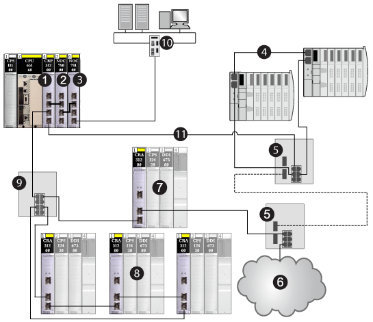
The following graphic shows a sample high-capacity daisy chain loop network configuration. Interlink the 140NOC78000 distributed I/O head module with the 140CRP31200 remote I/O head module in the local rack to support in the remote I/O network:
1
140CRP31200 remote I/O head module on the local rack
2
140NOC78000 distributed I/O head module (interlinked with the 140CRP31200 module to manage the distributed I/O sub-ring)
3
140NOC78100 control head module (interlinked with the 140NOC78000 module to monitor the entire Quantum EIO system
4
distributed I/O sub-ring
5
DRSs configured for copper-to-fiber and fiber-to-copper transition (connected to sub-rings)
6
distributed I/O cloud (managed by the 140NOC78000 module in the local rack)
7
Ethernet remote I/O drop (which includes a 140CRA31200 adapter module) on the main ring
8
Ethernet remote I/O drop (which includes a 140CRA31200 adapter module) on a remote I/O sub- ring
9
DRS (connected to a remote I/O sub-ring)
10
control network (connected to the 140NOC78100 module on the local rack)
11
main ring
NOTE: Download an appropriate predefined DRS configuration to each switch. Do not try to configure the switches yourself. The
predefined configurations have been tested so that they meet the determinism and cable redundancy standards of the Quantum EIO system.
Planning a Hot Standby System
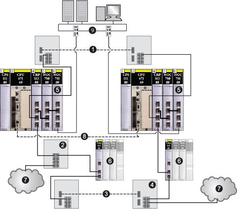
Just as in a , you can use a high-capacity daisy chain loop configuration in a Hot Standby system. Use one 140CRP31200 module on the primary local rack and one on the secondary local rack. The following figure shows a high-capacity daisy chain loop architecture of a Quantum EIO Hot Standby system. Refer to the Quantum Hot Standby System User Manual for details on setting up and maintaining the system as well the features available.
NOTE
A DRS predefined configuration, C15, is available for the switches that support a fiber link between the primary and standby controllers.
1
fiber cable used between 2 DRSs to extend the distance beyond 100 m between the Hot Standby controllers (this is optional)
2
DRS connecting a distributed I/O cloud to the main ring
3
fiber cable used between 2 DRSs to extend the distance between 2 remote I/O drops
4
DRS connecting a distributed I/O cloud to the main ring
5
primary and standby local racks (containing the controller, the power supply module, a 140CRP31200 remote I/O head module, a 140NOC78000 distributed I/O head module, and a 140NOC78100 control head module)
6
remote I/O drops (containing the 140CRA31200 adapter module and I/O modules)
7
distributed I/O clouds
8
fiber cable used for the CPU-sync link to expand the distance beyond 100 m
9
control network (connected to the 140NOC78100 module on the local rack)
NOTE: In the case of switchover in a Hot Standby configuration, the IP addresses of 140NOC78000 and 140NOC78100 modules change from IP to IP+1.

 WARNING