|


|
Original instructions
|
|
|
Original instructions
|
|
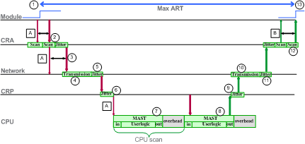
A: missed input scan
|
7: packet held in CRP queue (1 scan)
|
|
B: missed output scan
|
8: operation of application logic (1 scan)
|
|
1: input turns ON
|
9: CRP output jitter
|
|
2: CRA drop process time
|
10: network output time
|
|
3: CRA input request packet interval (RPI) rate
|
11: network output jitter
|
|
4: network input time
|
12: CRA drop process time
|
|
5: network input jitter
|
13: output applied
|
|
6: CRP input jitter
|
|
|
ID
|
Parameter
|
Max (ms)
|
Description
|
|
|---|---|---|---|---|
|
2
|
CRA drop process time (CRA_Drop_Process)
|
4.4
|
The sum of CRA input scan time and queue delay
|
|
|
3
|
CRA input RPI (RPI)
|
–
|
User defined. Default = 0.5 * CPU period if MAST is in periodic mode. If MAST is in cyclic mode, the default value is watchdog/4).
|
|
|
4
|
network input time2 (Network_In_Time)
|
2.496
(0.078 * 32)
|
The product of (network delay based on I/O packet size) * (the number of hops1 the packet travels). The network delay component can be estimated as follows:
|
|
|
I/O packet size (bytes):
|
Estimated network delay (μs):
|
|||
|
64
|
20
|
|||
|
128
|
26
|
|||
|
256
|
35
|
|||
|
400
|
46
|
|||
|
800
|
78
|
|||
|
1200
|
110
|
|||
|
NOTE: The value 2.496 ms is based upon a packet size of 800 bytes and 32 hops1 (33 hops in Hot Standby). |
||||
|
5
|
network input jitter (Network_In_Jitter)
|
6.436
((30 * 0.078) +
(32 * 0.128))
|
The formula is: ((number of RIO drops) * (network delay)) + ((number of distributed I/O hops1) * (0.128))
NOTE: The value 6.436 is based upon a packet size of 800 bytes. |
|
|
6
|
CRP input jitter (CRP_In_Jitter)
|
6.8
(0.6 + (31 * 0.2)
|
CRP input queue delay. The formula is either:
without Hot Standby: (0.6 ms + ((number of remote I/O drops) * (0.2 ms))
with Hot Standby: (0.6 ms + ((number of remote I/O drops + 1) * (0.2 ms))
|
|
|
7/8
|
CPU scan time (CPU_Scan)
|
–
|
This is the user defined Control Expert scan time, which can be either fixed or cyclic.
|
|
|
9
|
CRP output jitter (CRP_Out_Jitter)
|
1.6
|
CRP output queue delay.
|
|
|
10
|
network output time2 (Network_Out_Time)
|
2.496
|
Computed in the same manner as network input time, above.
|
|
|
11
|
network output jitter (Network_Out_Jitter)
|
3.968
(31 * 0.128)
|
Distributed I/O device packet output queue delay. The formula is:
(number of hops1) * 0.128
NOTE: This only applies if distributed I/O devices are connected to the remote I/O network. |
|
|
12
|
CRA drop process time (CRA_Drop_Process)
|
4.4
|
The sum of CRA queue delay and output scan time.
|
|
|
1. A hop is a switch that a packet passes through on the path from a source (transmitting) device, to a destination (receiving) device. The total number of hops is the number of passthrough switches along the path.
2. Regarding the optical fiber impact on network input time / network output time, the total length of the optical fiber that the I/O packet travels * 0.0034 ms/km (0.0054 ms/mi). Example: For 32 drops with 15 km (9.32 mi) of optical fiber (single mode) between drops, the impact is: 32 * 15 * 0.0034 = 1.6 ms.
|
||||
