Quantum EIO System Introduction
Original instructions
Introduction
PlantStruxure is a Schneider Electric program designed to address the key challenges of many different types of users, including plant managers, operations managers, engineers, maintenance teams, and operators, by delivering a system that is scalable, flexible, integrated, and collaborative.
This document presents one of the PlantStruxure features, using Ethernet as the backbone around the Quantum PLC offer and connecting a Quantum local rack to Quantum and Modicon X80 remote I/O drops and distributed I/O devices. This feature is known as Quantum Ethernet I/O or Quantum EIO. (NOTE: Modicon X80 is the generic name given to the M340 I/O modules when they are connected remotely to a Quantum controller or module in a PlantStruxure architecture. The M340 I/O name is still used when the module is connected to a M340 controller. The product references remains unchanged; only the range name changes.)
A Quantum EIO system integrates a unique standalone PLC or a unique Hot Standby system.
WARNING
UNEXPECTED EQUIPMENT BEHAVIOR
  • Do not install more than 1 standalone PLC in a Quantum EIO network.
  • Do not install more than 1 Hot Standby system in a Quantum EIO network.
Failure to follow these instructions can result in death, serious injury, or equipment damage.
The system is designed and tested for simultaneous use of:
The Quantum EIO system provides automatic network recovery of less than 50 ms and deterministic remote I/O performance.
NOTE: A Quantum EIO system uses the same Quantum I/O modules as a Quantum legacy remote I/O system (S908).
Quantum EIO Architecture
The following graphic outlines a typical Quantum EIO architecture, encompassing the enterprise, plant, process, and field levels of a manufacturing plant.
Quantum EIO Life Cycle
A Quantum EIO network offers the following features for each phase in the life cycle of the system.
Life Cycle Phase
Feature
Description
design phase
standard
reduce the learning and engineering time
open
collaborate with third-party solutions
flexible
adapt the control architecture to the plant topology
efficient
design the solution without constraints
operation phase
transparent
provide access to I/O modules and devices from the control network
highly available
reduce process downtime
renew phase
sustainable
preserve long-term investment, allow smooth migration
Quantum EIO Example
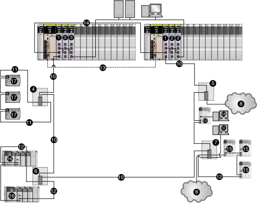
The following graphic is an example of a viable Quantum EIO network, integrating remote I/O devices and distributed I/O devices, within a Quantum Hot Standby system.
1 
140 CRP 312 00 remote I/O head module on the local rack
2 
140 NOC 780 00 distributed I/O head module (connected to the 140 CRP 312 00 head module)
3 
140 NOC 781 00 control head module on the local rack (connected to the 140 NOC 780 00 head module)
4 
DRS (connected to a distributed I/O sub-ring)
5 
DRS (connected to a distributed I/O cloud)
6 
DRS (connected to a remote I/O sub-ring)
7 
DRS (connected to a remote I/O sub-ring, distributed I/O cloud, and PC/port mirror)
8 
distributed I/O cloud
9 
PC for port mirroring
10 
main ring
11 
distributed I/O sub-ring
12 
remote I/O sub-ring
13 
CPU-sync link
14 
140 CRP 312 00 head module-sync link
15 
Quantum remote I/O drops (including a 140 CRA 312 00 adapter module)
16 
Modicon X80 remote I/O drops (including a BMX CRA 312 10 adapter module
17 
distributed I/O devices (STB NIP 2311 NIM on an STB island)
18 
Control Expert connection using the service port on the 140 CRA 312 00 adapter module
NOTE: If you use a low-end CPU (140 CPU 6• 1••) (2 Mb or less), you can only install a maximum of 31 remote I/O drops. Of those 31 drops, you can only install a maximum of sixteen BMXCRA312•0 remote I/O drops. If you use a high-end CPU (140 CPU 6•• ••) (4 Mb or more), you can install a maximum of thirty-one BMXCRA312•0 or 140CRA31200 remote I/O drops.