Planning the Appropriate Network Topology
Original instructions
Key Points when Planning a Topology
Consider the following key points when choosing a Quantum EIO network topology:
These points are discussed in the following paragraphs.
Providing Transparency Between Quantum EIO Networks
The 140NOC78100 control head module uses an IP forwarding service to provide transparency between networks in a Quantum EIO system. The IP forwarding service of the 140NOC78100 module is the interface between the control network and the other network (i.e., device network, extended distributed I/O network), with which you want to provide transparency.
NOTE: Use Control Expert to configure the IP forwarding service. For details, refer to the Configuring the IP Forwarding Service topic in the Quantum Ethernet I/O Control Network Installation and Configuration Guide.
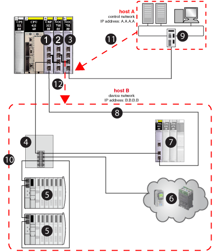
As an example, suppose you want to provide transparency between the control network and the device network:
In order for hosts A and B to communicate with each other, connect the control network and device network physically, as well as logically. The IP forwarding service in the 140NOC78100 module is the interface for the network connection.
The IP forwarding service gathers 3 types of information:
The IP forwarding service now has interface A with an IP address of A.A.A.1 on the control network, and it has interface B with an IP address of B.B.B.1 on the device network.
With this information, the routing table used for IP address forwarding looks like this:
Network
Interface
A.A.A.0 (control network)
A.A.A.1
B.B.B.0 (device network)
B.B.B.1
Now that you have established the IP forwarding service (i.e., gateway), add the IP address forwarding information to hosts A and B, which allows the hosts to send packets beyond their own IP network.
At this point, you can assume that host A is aware of host B and that host A wants to send a packet (example: Modbus message) to host B. Host A (IP address A.A.A.A sends the message to interface A (IP address A.A.A.1), which then sends it to interface B (IP address B.B.B.1) and finally to host B (IP address B.B.B.B) (as shown in the following graphic):
1 
140CRP31200 remote I/O head module on the local rack
2 
140NOC78000 distributed I/O head module (interface B)
3 
140NOC78100 control head module (interface A)
4 
DRS (with a C2 predefined configuration file loaded) connecting the distributed I/O sub-ring (5) and the distributed I/O cloud (6) to the main ring (8)
5 
distributed I/O sub-ring
6 
distributed I/O cloud
7 
remote I/O drop on the main ring
8 
main ring
9 
control network (host A)
10 
device network (host B)
11 
control network (host A) with IP address A.A.A.A sends the message to interface A (140NOC78100 module) with IP address A.A.A.1
12 
interface B (140NOC78000 module) sends the message to the device network (host B) with IP address B.B.B.1
Distance Between 2 Remote I/O Devices
The distance between 2 Ethernet remote I/O devices determines the choice of physical layer.
If you are using copper cable, the maximum distance between 2 contiguous remote I/O devices is 100 m. If contiguous devices are more than 100 m apart, use 1 or more DRSs. A DRS can be used to extend a copper cable run or to transition the main ring from copper to fiber. You can also install NRP fiber converter modules to convert copper cable to fiber. A fiber cable can run as long as 15 km (for single-mode fiber).
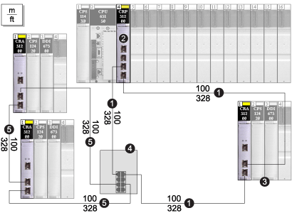
If Distance Between 2 Remote Devices is Less than 100 M...
A copper Ethernet network provides a valid solution.
Note 
The solid line represents copper wire.
1 
the main ring
2 
the 140 CRP 312 00 head module in the local rack
3 
a remote I/O drop (including a 140 CRA 312 00 adapter module) on the main ring
4 
a DRS with a C1 predefined configuration to support a remote I/O sub-ring
5 
a remote I/O sub-ring
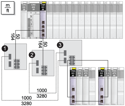
If Distance Between 2 Remote Devices is More than 100 M...
DRSs may be used to extend the cable run or convert copper cable to fiber. To connect the fiber to the copper cables, insert a DRS at each end of the fiber link. Thus, 2 DRSs are required for 1 fiber link.
Note 
The dashed line represents fiber cable, and the solid line represents copper wire.
1 and 2 
2 DRSs with C5 predefined configurations to use only 1 fiber port. They support a copper-to-fiber and a fiber-to-copper transition. They enable the fiber-based network to connect to the copper ports on the 140 CRP 312 00 head module in the local rack.
3 
A DRS with a C3 predefined configuration to use 2 fiber ports and support a remote I/O sub-ring and a distributed I/O cloud.
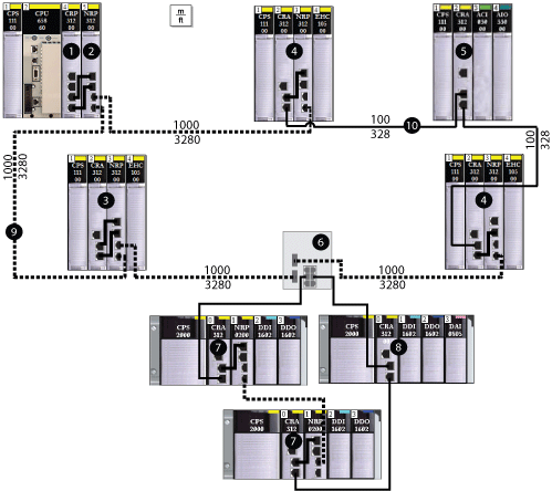
140 NRP 312 00/01 and BMX NRP 0200/01 fiber converter modules may be used to extend the cable run or convert copper cable to fiber.
The following graphic shows 140 NRP 312 00/01 fiber converter modules on Quantum remote I/O drops used to extend the distance between drops beyond 100 m. The remote I/O sub-ring includes X80 drops with BMX NRP 0200/01 fiber converter modules used to extend the distance between drops beyond 100 m.
1 
Quantum local rack, showing a 140CRP31200 head module copper connection to the 140 NRP 312 00/01 fiber converter module (2)
2 
140 NRP 312 00/01 module connected to the local rack via fiber cable
3 
Quantum remote I/O drop connected to the main ring via fiber cable (140 NRP 312 00/01 module installed on drop)
4 
Quantum remote I/O drop connected to the main ring via copper and fiber cable (140 NRP 312 00/01 module installed on drop)
5 
Quantum remote I/O drop connected to the main ring via copper cable (no 140 NRP 312 00/01 module installed on drop)
6 
dual-ring switch (DRS) connecting the X80 sub-ring to the main ring
7 
X80 remote I/O drop connected to the main ring via copper cable and connected to the next drop in the sub-ring via fiber cable (BMX NRP 0200/01 fiber converter module installed on drop)
8 
X80 remote I/O drop connected to the next drop in the sub-ring and the main ring via copper cable (no BMX NRP 0200/01 module installed on drop)
9 
(dashed line) — fiber portion of the main ring
10 
(solid line) — copper portion of the main ring
NOTE:
  • Use multi-mode fiber to connect NRP modules if the distance between them is less than 2 km.
  • Use single-mode fiber to connect NRP modules if the distance between them is greater than 2 km and less than 15 km.
  • You cannot use fiber converter modules to connect remote I/O or distributed I/O sub-rings to the main ring.
High Availability Requirements
If high availability is required on the remote I/O network, the Quantum EIO system supports a Hot Standby solution. Refer to the Quantum Hot Standby System User Manual for details on setting up and maintaining the system as well as the features available.
Topology Choices
Your Ethernet remote I/O network will comprise of one of the following topologies:
These 2 topologies, which are discussed later in this guide, are comprised of the devices in the table below. These devices and their Ethernet port types define how you will choose and build your topology.
To Insert in the Network...
Use...
Topology Type
distributed I/O devices with a single Ethernet port
a distributed I/O cloud (with devices in a star topology)
You can connect a distributed I/O cloud to a high-capacity daisy chain loop.
  • A distributed I/O cloud participates in the remote I/O network only if it is connected to a DRS that resides on the main ring in a high-capacity daisy chain loop. In this case, interlink a 140CRP31200 remote I/O head module with a 140NOC78000 distributed I/O head module on the local rack, since the 140NOC78000 module supports the distributed I/O cloud.
NOTE: A distributed I/O cloud that is connected to a 140NOC78000 module on the local rack within a simple daisy chain loop is isolated. The cloud is not physically part of the remote I/O network.
distributed I/O devices with dual Ethernet ports
  • a distributed I/O cloud (with devices in a star topology)
    — or —
  • a distributed I/O sub-ring (with devices in a daisy chain loop, if they support RSTP).
You can only connect a distributed I/O cloud or distributed I/O sub-ring via a DRS that resides on the main ring in a high-capacity daisy chain loop.
remote I/O devices with dual Ethernet ports
a Quantum remote I/O drop on the main ring or a remote I/O sub-ring
Local Rack Configuration Based on Topology
To plan the head modules to install and interlink on the local rack, refer to the Local Rack Head Module Connectivity topic.
Distributed I/O Devices
The number and location of distributed I/O devices in the network impact the module choice.
If Distributed I/O Devices Are in a...
Then...
isolated distributed I/O network or cloud — distributed I/O devices that are not a physical part of the remote I/O network
One or more 140NOC78000 distributed I/O head modules are required to manage the distributed I/O devices.
Each 140NOC78000 module can manage up to 128 isolated distributed I/O devices.
NOTE: A local rack manages a maximum of 6 communication modules. A 140CRP31200 remote I/O head module is not considered a communication module. You can install a maximum of five 140NOC78000 modules and one 140NOC78100 control head module. Instead of 140NOC78000 modules, you can also install 140 NO• 771 •• or 140 NOM 2•• 00 communication modules.
distributed I/O sub-ring or cloud — distributed I/O devices that are a physical part of the remote I/O network
In addition to a 140CRP31200 remote I/O head module on the local rack:
  • One 140NOC78000 distributed I/O head module in the local rack is connected to the 140CRP31200 module via the interlink port to manage the distributed I/O devices.
  • One or more DRSs may be necessary to create distributed I/O sub-rings or clouds. The distributed I/O devices cannot be connected directly to the main ring.
The 140NOC78000 module (interlinked with the 140CRP31200 module) can manage up to a total of 128 devices in the remote I/O network.
NOTE: A local rack manages a maximum of 6 communication modules. A 140CRP31200 remote I/O head module is not considered a communication module. You can install a maximum of five 140NOC78000 modules and one 140NOC78100 control head module. Instead of 140NOC78000 modules, you can also install 140 NO• 771 •• or 140 NOM 2•• 00 communication modules.
extended distributed I/O network or cloud — distributed I/O devices that do communicate with the Quantum EIO device network
Interlink a 140NOC78000 distributed I/O head module with the extended port of the 140NOC78100 control head module. The 140NOC78100 is also interlinked with the 140CRP31200 remote I/O head module.
NOTE: Only one extended distributed I/O network is supported in a Quantum EIO system.
independent distributed I/O network or cloud — distributed I/O devices that do not communicate with the Quantum EIO device network, but do communicate with the control network
Interlink a 140NOC78000 distributed I/O head module with a 140NOC78100 control head module on the local rack. These modules are not interlinked with the 140CRP31200 remote I/O head module. An independent distributed I/O network is essentially an isolated distributed I/O network, but it communicates with a Quantum EIO control network.
NOTE: Only one independent distributed I/O network is supported in a Quantum EIO system.
Isolation Requirements
DANGER
ELECTRICAL SHOCK HAZARD
  • Switch off the power supply to the automation controller stations at both ends of the connection before inserting or removing an Ethernet cable.
  • Use suitable insulation equipment when inserting or removing all or part of this equipment.
Failure to follow these instructions will result in death or serious injury.
If isolation is required in your network (e.g., if the local rack and remote I/O drops are on different grounding systems), then use fiber cable to connect devices that are on separate grounding systems.
Refer to the ground connections information in Electrical installation guide to comply with EMC certifications and deliver expected performance.
Redundancy Requirements
Two DRSs can be used to provide a redundant connection between the main ring and the sub-ring. One DRS is installed with a master predefined configuration, and the other is installed with a corresponding slave predefined configuration. The master DRS passes data between the main ring and the sub-ring. If the master DRS becomes inoperable, the slave DRS takes control and passes data between the main ring and the sub-ring. For details, refer to the Predefined Configuration Files chapter.