

Overview
The first time you open a system project, the opens.
Thereafter, you can open a physical view either way:
By double-clicking it in the node of the pane.
By clicking in the submenu of a device.
The physical view lets you design in a graphical way the hardware architecture (which is composed of devices and racks of M580 PACs), connect the ports of devices and modules, and view network-related information of devices.
You can add equipment to a physical view either from the or from the pane.
You can create additional physical views in the pane and move devices between physical views.
Description
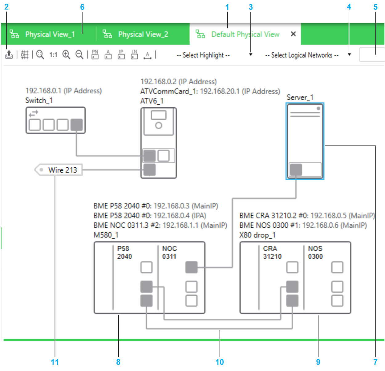
The following figure shows an example of a physical view of a system project.
| Item | Description |
| 1 | Tab of the physical view that is active. |
| 2 | Toolbar of the physical view. Buttons that have a toggle function are highlighted when the command is enabled. For details, refer to the description of the context menu commands of the physical view workspace. |
| 3 | List, which lets you identify graphically one of the following in the physical view: Select or close the physical view to remove highlights. |
| 4 | List, which lets you select one or more existing logical networks and highlight the objects that belong to them. |
| 5 | Search field, which lets you locate objects, such as devices, modules, ports in the physical view that is active. |
| 6 | Tabs of other physical views that are open. |
| 7 | Representation of the device. The highlighted outline indicates that it is selected. |
| 8 | Representation of the local rack of an M580 PAC whose configuration has been modified by editing its control project with Control Expert Editor. |
| 9 | Representation of the drop of the PAC. You can reposition it, remove it from the view, or add it to another physical view. |
| 10 | Physical link connecting the ports of two devices located in the same physical views. |
| 11 | Connector of a physical link connecting the ports of two devices located in different physical views. |
Workspace Actions
The actions that you can perform by using the commands that are described in this table apply to each physical view individually. Modifications to the appearance or the behavior are persisted when you close the Topology Manager and reopen the system project on the same computer.
The table describes the commands of the context menu of the physical view workspace.
Command |
Description |
|
|---|---|---|
|
Enables a functionality that lets you position devices by aligning them with an invisible grid. |
|
|
Opens a submenu that lets you modify the zoom level of the view. |
|
|
|
When selected, shows the attribute of devices and PACs. For devices for which you have selected a DTM at the time of creation, the DTM attribute is displayed. The name is displayed above each device, left-aligned. |
|
When selected, shows the attribute of devices. The name is displayed above each device, left-aligned. |
|
|
When selected, shows the attribute of physical links. The label is displayed approximately in the middle of the link length with an orientation that is parallel to the link. |
|
|
When selected, shows IP addresses and logical networks of devices and modules respectively. The information is shown on top of the label of the device (if shown). When both are selected, the format is Name: logical network/CIDR - IP address (IP address name), where:
For example, for a CPU module of an M580 PAC, BMEP582040 #0: MyNetwork/16 - 192.168.0.2 (MainIP) NOTE: The following applies to
the display of network data:
|
|
|
||
|
Refer to the topic describing the command. |
|
|
Lets you save to a file the layout of the entire physical view independently of the current zoom level. The complete data that appears in the workspace (for example, objects, links, names of objects, highlights) is captured. It enables you to open the graphical layout by using a CAD software. You can create files of the following types:
|
|
The following figure shows an example of the information that is displayed for a local rack when the display of names, IP addresses, and logical networks is enabled.
Identification of Port Types
When you select from the list, ports are shown in a specific color depending on the type of network that they support.
Network type |
Color |
|---|---|
DIO |
Orange |
RIO |
Green |
Identification of Redundant Networks
When you select from the list, the redundant ports of the following devices are shown in a specific color.
Network type |
Color |
Device |
Port |
|---|---|---|---|
Primary network |
Red |
BMECRA31310 adapter module |
ETH2 |
Hirschmann switches |
Port1 |
||
Redundant network |
Blue |
BMECRA31310 adapter module |
ETH3 |
Hirschmann switches |
Port2 |
In addition, physical links that connect ports of the same color are shown in that color. The link must be direct or connect in between ports of one or more ConneXium switches that are configured as type.
Physical links connecting ports that belong to different redundant networks are shown in black. Analyze the system project to obtain details.
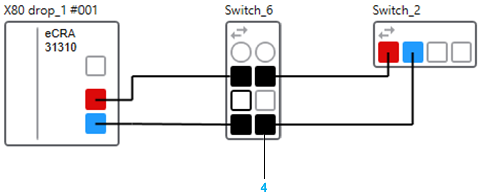
The following figures show some examples of physical links connecting redundant ports.
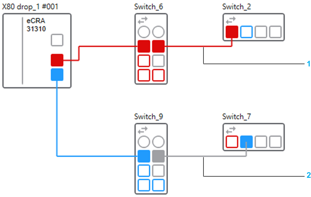
| Item | Description |
|---|---|
1 |
Links connecting the redundant port of a module, a ConneXium switch (Switch_6), and a Hirschmann switch. The ports of the ConneXium switch that are of type are also shown in red. |
2 |
Link that is shown in gray because port 4 of the ConneXium switch (Switch_9) is of type . |
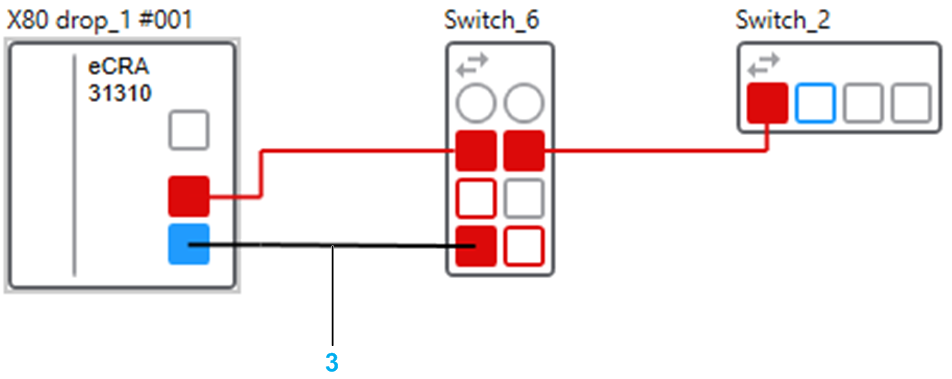
3 |
Link that is shown in black because of an incorrect connection. Port 7 of the ConneXium switch (Switch_6) is connected to a blue redundant port while its other ports already belong to a red redundant network. |
4 |
Ports and links of the ConneXium switch (Switch_6) are shown in black because of a redundant network conflict. Two different redundant networks are connected to the switch. |
Device Actions
The table describes the commands of the context menu of a device that are specific to physical views. For a description of the other commands, refer to the topic describing the device context menu.
Command |
Description |
|---|---|
|
Refer to the topic describing the command. You cannot cut or copy the local rack or drop of an M580 PAC in a physical view. Use command from the PAC in the pane. |
|
|
|
Refer to the topic describing the command. |
|
Removes only the representation of the device (or the selection of devices) from the physical view. Ports that this device is connected to remain connected and are specially identified. The corresponding physical links are hidden but appear again when the device is added to a physical view again. NOTE: If you want ports
that the device is connected to to remain available for connection,
remove the links before removing the device from the view.
|
Locating Objects by Using the Search Field
The search field lets you locate the following objects by typing their entire or part of their name:
Devices
Modules
Network interface cards
Ports
Physical links
The search field is not case-sensitive and you do not need to use wildcards.
The full name of objects whose name contains the string are displayed in a list as you type. Results are listed in ascending alphanumeric order.
To locate an object from the list, double-click it. The object is shown centered in the physical view. To locate several objects, select each one in the list, then double-click any one of them. Objects that are selected in the list remain selected until you clear them by clicking them again.
The list of results remains available until you clear the search field. To show the list again, click inside the search field (if it has lost the focus) and press the key.
You can also use the following keys with the search field.
Key |
Action |
|---|---|
The key |
Shows and/or enters the list of results. Once in the list, lets you move down the list. The object that has the focus is highlighted. |
The key |
Lets you move up in the list of results. |
The key |
Selects a highlighted object. To clear a selected object, put the focus on the object again and press the key. |
|
Locates the selected objects in the physical view. |
Multiselection of Devices
When you select multiple objects in a physical view, the pane shows the tabs and attributes that the objects have in common.