

Overview
You can open the either way:
By clicking in the context menu of the system project name, the node, or a logical network in the pane.
By clicking in the submenu of a device.
By using the menu in the toolbar.
It gives you an overview of the network configuration of devices that exist in your system project and that manage at least one IPv4 address. As such, it facilitates the management of many devices at system project level.
The view is refreshed when you or other users modify the configuration of objects that are shown.
Description
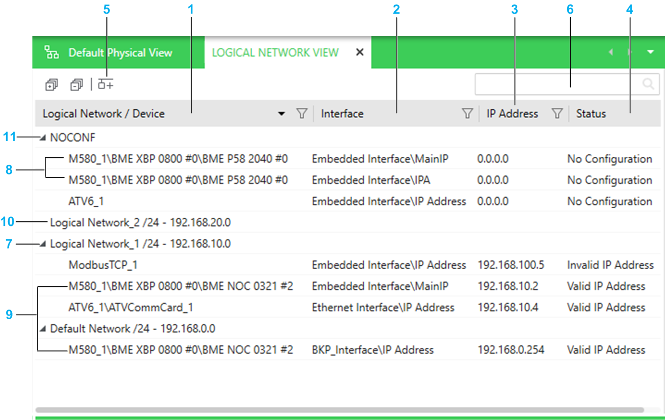
The following figure shows an example of the of a system project.
Item |
Description |
|---|---|
1 |
The column shows the name of the following objects that exist in the system project:
|
2 |
Name of the interface of the device to which an IP address is assigned. When the interface manages several IP addresses, their name is indicated. The following syntax is used in this column to identify interfaces and their IP addresses:
|
3 |
IP address that is assigned to the interface. You can modify the address. |
4 |
Indicates the validity of the IP address in relation to the logical network that the interface belongs to. Possible values:
|
5 |
Lets you create a logical network. |
6 |
Search field. Enter one or more terms separated by a space and the window displays objects whose name contains any of these terms. Objects are displayed with the logical network they belong to. |
7 |
Entries are grouped by logical network. The logical network group indicates the name of the logical network that the interface belongs to. In addition, the CIDR notation suffix and address of the network are indicated. You can change the logical network assignment but you cannot create logical networks in this view. |
8 |
For devices that manage several IP addresses, an entry is displayed for each one of them. The entry appears under the respective logical network group. |
9 |
Interfaces pertaining to a same device appear under different logical network groups if the assignment of their respective interfaces is different. |
10 |
Existing logical networks to which no interface is assigned are also shown. |
11 |
Interfaces for which no logical network is defined are shown in the group. |
Context Menu Commands
The table describes the commands of the context menu of a device that are specific to the . For a description of the other commands, refer to the topics describing the context menu commands for logical networks and devices.
| Command | Description |
|---|---|
|
Lets you replace the invalid IP address of the selected interfaces with the next available IP address on the logical network. If the status of an address is , it remains unchanged except if it is not unique, in which case the software assigns the next available IP address to the interface. When you select several interfaces in the view, IP addresses are reassigned in the order that you have selected the interfaces. Within a logical network, when you select all the interfaces that have a same IP address, the IP address of the interface that you have selected first is unchanged (given it is valid). NOTE: If you select several interfaces to reassign
their IP addresses and not enough IP addresses are available, the
reassignment of IP addresses is done only partially and a notification
is displayed.
|
Multiselection of Entries
When you select multiple entries in the , the pane shows the tabs and attributes that the devices have in common.