

Overview
Each equipment or device that you add to a physical view is represented by one or more graphical objects.
Controllers of platforms other than M580 are represented by the same single object independently of their configuration.
This topic describes how various types of objects are represented in a physical view.
Devices
The following figure shows an example of a device that has been created by using a managed switch of the product range.
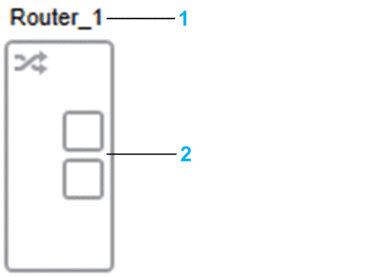
| Item | Description |
| 1 | Name of the device. Additional information can be shown. |
| 2 |
The following figure shows the same device but with its attribute set to true (selected). The device is shown in a lighter shade of gray.
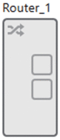
The name
IP addresses
Logical networks
Devices Containing Modules
Devices that contain modules, which have Ethernet connectivity features a distinct graphical area, which represents the module and that you can select individually. It lets you view properties and open a context menu that are specific to the module.
The following figure shows an example of devices that contain a module.
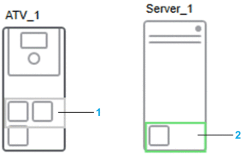
| Item | Description |
| 1 | Graphical area that represents the communication card of a drive. The outline of the area is highlighted when you hover over it with the pointer. |
| 2 | Graphical area that represents the NIC of the server station. Click the empty space inside the area to make it active and view properties of the NIC. Right-click it to open a context menu. |
M580 PACs
In a physical view, the local rack and drops of standalone and redundant M580 PACs are represented as distinct objects.
The following figure shows an example of how an M580 PAC is represented in a physical view.
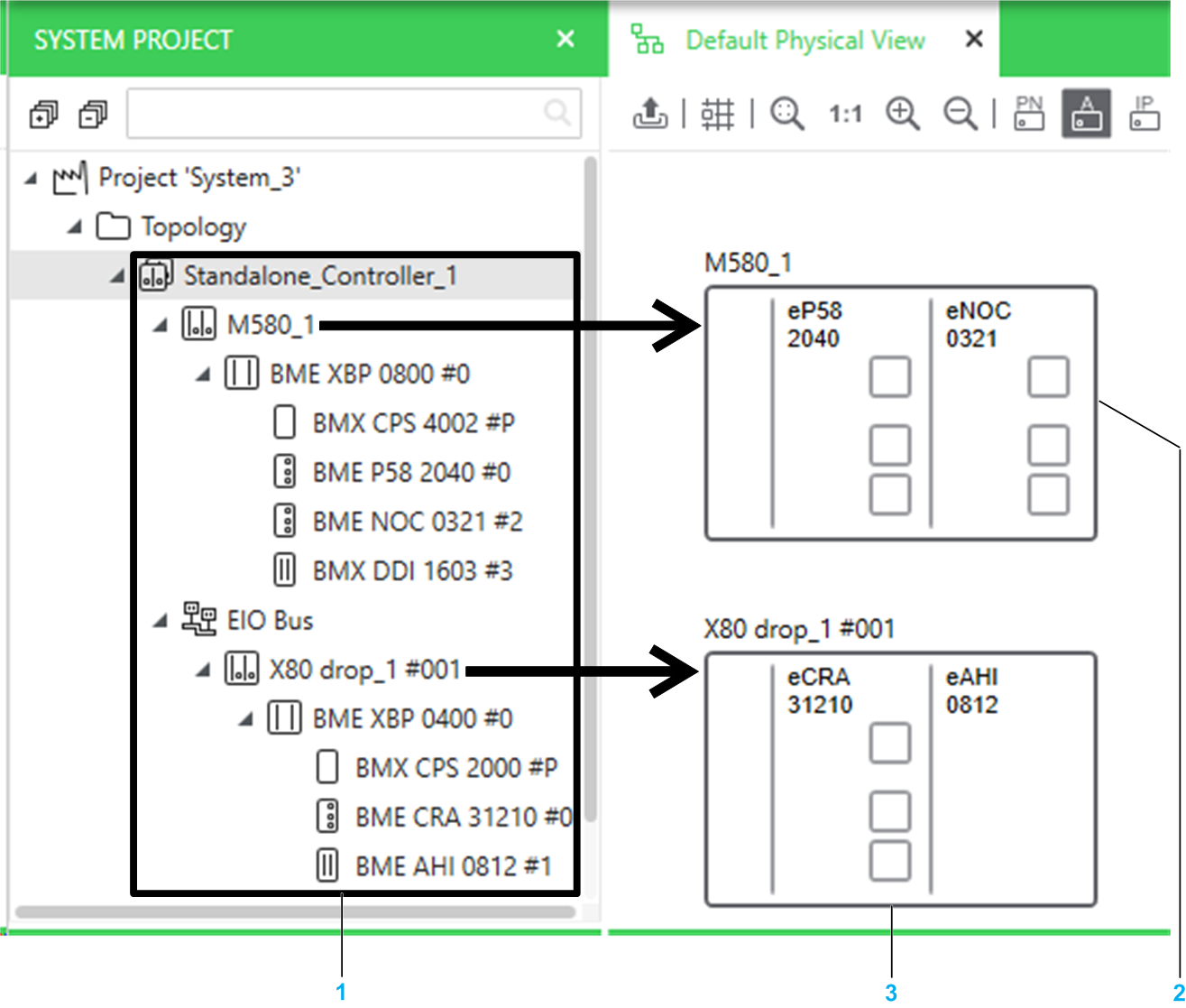
| Item | Description |
|---|---|
1 |
The PAC represented by the Standalone_Controller_1 node in the pane. |
2 |
The local rack. |
3 |
The drop. |
A rack or drop is composed of several graphical areas, which you can select individually. Areas represent modules that have Ethernet connectivity (for example, the CPU module for a local main rack, the adapter module for a remote rack, or a communication module). Modules may not be represented in their actual position on the backplane. Modules let you open a menu containing commands that are specific to the selected module.
To view the modules and their position, open the rack or drop of a PAC by using the .
When you modify the configuration, the representation of the device is updated in the physical view depending on the nature of the change (for example, extended racks and their modules are not shown).
When you add a drop to a PAC whose local rack already appears in a physical view, the drop is automatically added to the same physical view. It overlaps the local rack and you need to reposition it.
The following figure shows an example of the local rack and drop that are displayed when you drag a standalone M580 PAC to a physical view. The drop has been repositioned.
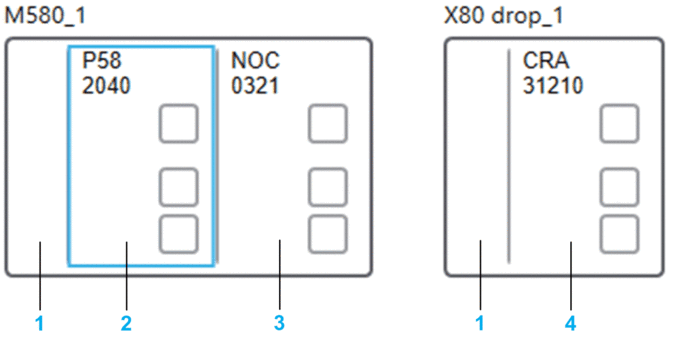
| Item | Description |
| 1 | Handle, which lets you move the rack and open a context menu. |
| 2 | Area that represents the CPU module. The highlighted outline indicates that only the CPU module is selected. Right-click it to open the context menu of the module and the PAC. |
| 3 | Area that represents a communication module that has been added by editing the control project. |
| 4 | Area that represents the adapter module of the drop. |
The following figure shows an example of the two local racks and the high-speed cable link that are displayed when you drag a redundant M580 PAC to a physical view. If drops exist, they are displayed as well.
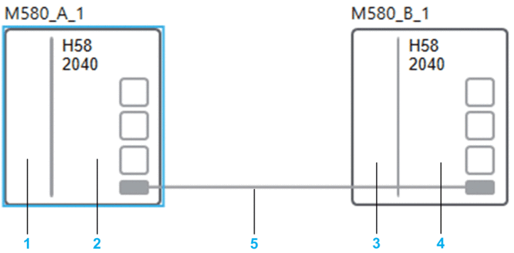
| Item | Description |
| 1 | Handle of local rack A. The rack is shown selected. |
| 2 | CPU module. |
| 3 | Handle of local rack B. The rack is automatically positioned at a distance and you can move either rack individually. |
| 4 | CPU module. |
| 5 | High-speed cable link represented by a solid line. You can enter a label, modify the routing, but not delete the link. |