Overview
After you have added at least two devices to a physical view of your system project, you can connect their communication ports by a physical link. This link represents a cable connection. A color coding indicates the types of networks.
You can connect ports of devices that appear in the same or in different physical views.
Once you have created the connection, the software draws the path of the physical link automatically. You can change the routing of the link manually.
When you reposition a connected device in a physical view or move it to another one, physical links are redrawn as needed to adapt to the new layout. You may need to rework links that you have routed manually.
The high-speed cable link that connects the local racks of a redundant PAC is considered a physical link but some of the functionality described in this topic may not apply to it.
Connection Rules
The following rules apply when you connect devices by a physical link:
A link can create only a one-to-one connection between two ports of the same or distinct devices.
Each port can be connected only once.
If you connect devices that appear in different physical views:
One of the ports to be connected by a physical link must be tagged for connection.
The two physical views must be open.
Port Status and Physical Link Representation
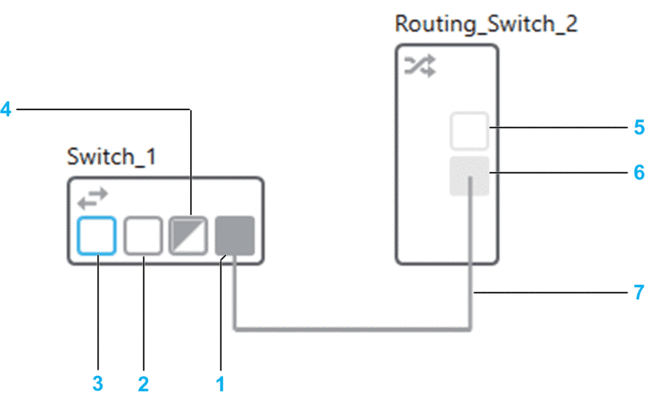
The following figure shows an example of the representation of two devices with various port configurations in a physical view. The devices are connected by a physical link.
| Item | Description |
| 1 | Linked port |
| 2 | Port available for connection (port enabled) |
| 3 | Port that is tagged for connection |
| 4 | Port that is connected to a device that has been removed from the physical view. The port is not available for connection anymore. |
| 5 | Port available for connection (port disabled) |
| 6 | Disabled and linked port |
| 7 | Physical link |
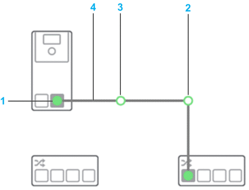
The following figure shows an example of a physical link that is selected.
| Item | Description |
| 1 | Link endpoint |
| 2 | Joint created by the software |
| 3 | User-created joint |
| 4 | Segment of the link (portion of the link that is between two joints or a joint and an endpoint) |
Remote Link Representation
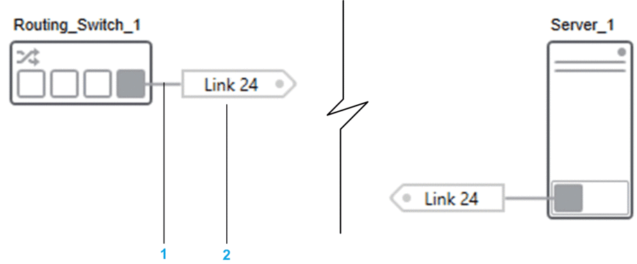
The following figure shows an example of a remote link between a switch and a server station that are located in the same or different physical views. When devices are located in the same physical view, showing the link as a remote link is optional.
| Item | Description |
| 1 | Physical link stub |
| 2 | Connector. The same connector is shown for each of the two connected ports. To rename it, edit its attribute in the PROPERTIES pane. |
A tooltip indicates:
The value of the attribute. If blank, a numerical ID is shown.
The destination of the link in the format physical view name\device name\port name where:
physical view name is shown only if the device is located in a different physical view.
device name can be followed by the name of one or more child objects in case of racks. For example, Standalone_Controller_2\M580_1\BMEXBP0800 #0\BMEP582040 #0 where Standalone_Controller_2 is the name of the PAC object (device) and M580_1 the local rack.
Port Name, Anchors, and Link Direction
The name of a port is indicated by a tooltip when you position the pointer over the port.
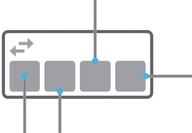
Each port has five anchors from which you can start a link or to which you can connect a link.
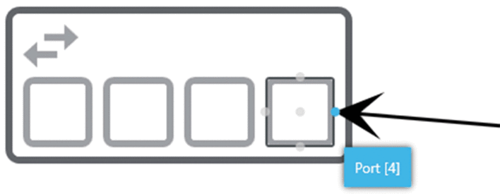
The anchors appear only on the target port when you position the pointer over it.
The anchor that you select to start or connect the link dictates the initial direction of the link. When you select the center anchor, the software routes the link automatically.
The following figure shows four links connected to different anchors of ports and the resulting link direction as an example.
Port Actions
Right-click the available port of a device to open a context menu containing the following commands (the port can be in disabled state).
Command |
Description |
|---|---|
|
When selected, lets you connect the port from a device located in another open physical view. The name of the port appears in a submenu of the command when you select the command on the other device. NOTE:
|
|
Lists the ports of devices that are tagged for connection. The devices are those of the current system project that have been added to a physical view that is open. If has not been selected for any port, the command is unavailable. Ports are shown by using the format physical view name\device name\port name where:
NOTE: Once you have connected one of the listed ports,
it is not tagged for connection anymore.
|
Connecting Ports of Devices in the Same Physical View
To connect two ports by a physical link, proceed as follows.
Step |
Action |
|---|---|
1 |
In a physical view, position the pointer over the center or one of the edges of a port, which is available for connection. Result: A link symbol appears next to the pointer. |
2 |
Press and hold the left mouse button and drag the pointer away from the port. Result: A line with arrow end is drawn. |
3 |
You can release the mouse button and move the arrow over the port that is the target for the connection. Result: The anchors of the port are shown. NOTE: To cancel the link drawing, press .
|
4 |
Move the arrow over one of the anchors of the port so that it is highlighted and click it. Result: The port is connected and the link between the devices is drawn. The link is shown selected, which lets you view endpoints and joints. |
Connecting Ports of Devices Appearing in Different Physical Views
To connect two ports by a physical link when devices are located in different physical views, proceed as follows.
Step |
Action |
|---|---|
1 |
In one of the physical views, right-click the port of a device and select . Result: The port is outlined. |
2 |
In the other physical view, right-click the port to be connected and select . Result: The name of the port that is tagged for connection is shown. (Any other port that is tagged for connection appears as well.) |
3 |
Select the port. Result: A remote link is created between both ports in each physical view. The software selects the anchors automatically. |
Changing the Connected Port or Routing of an Existing Physical Link
To connect either endpoint of an existing physical link to another available port, select the endpoint and drag it to the other port. The physical link is rerouted automatically; manual changes to the route and joints that you have added are discarded.
You can also modify the route of a link. The following figure shows the automatically routed link from the previous example, which has been rerouted manually by dragging the left-hand joint to a new position. The joint is shown selected. This action disables the automatic routing feature of the link.
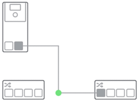
For remote links, you can drag the connector to a new position.
Physical Link Actions
Right-click a physical link or the stub of a remote link to open a context menu containing the following commands.
Command |
Description |
|---|---|
|
Inserts a joint where you have right-clicked the link. It creates two segments and lets you:
NOTE: Deleting a joint aligns the two segments again.
|
|
Opens a submenu that lets you configure in which direction the link exits the port from which it originates. You can use it, for example, to change the default routing of links. For a description of the submenu entries, refer to the topic describing physical link properties. NOTE: You can use the port anchors instead.
|
|
Opens a submenu that lets you configure in which direction the link enters the port to which it is connected. You can use it, for example, to change the default routing of links. For a description of the submenu entries, refer to the topic describing physical link properties. NOTE: You can use the port anchors instead.
|
|
Selected by default after you create the link. Cleared if you add a joint or change the routing of the link. Selecting it again discards changes and routes the link automatically. |
|
When selected, shows only both ends of the physical link. Each stub ends with a connector that displays the five first characters of the label. When you clear the check box, a solid link is redrawn and the tag removed. Other existing links may be repositioned as needed. NOTE: The command is
selected and disabled for remote links connecting devices that are
located in different physical views.
|
|
Deletes the link and makes the ports that were connected available again. You need to confirm the command. For remote links, also deletes the counterpart link in the other physical view. |
Remote Link Connector Actions
Right-click the connector of a remote link to open a context menu containing the following commands.
Command |
Description |
|---|---|
|
Shows the device that is connected at the other end and highlights the counterpart connector in the physical view. If it is located in another physical view, it is opened and/or made active. You can also double-click the connector. |
/ |
Defines the orientation of the connector. NOTE: Corresponds to the attribute of the
connector.
|
|
Deletes the connector, the link, and their counterparts in the other physical view after you confirm the command. |
Physical Link Properties
Click a physical link or the stub of a remote link to display its properties in the tab of the pane.
You can view and/or edit the following properties of the category.
Attribute |
Description |
|---|---|
|
Click the field to edit the name. The name does not need to be unique in the system project. NOTE: When you enter a value, it is used as
label for the link in the physical view. You can show or hide the label.
|
|
The following settings let you configure how the link exits the port from which it originates. The link is connected to the corresponding anchor.
|
|
The following settings let you configure how the link enters the port to which it is connected. The link is connected to the corresponding anchor.
|


