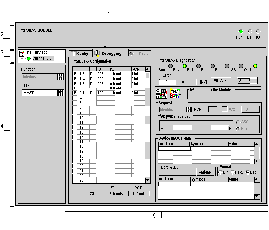
The Debug function, or double-clicking on the TSX IBY 100 graphic module in the Control Expert configuration, is only available in online mode.
NOTE: In online mode, if your project contains an INTERBUS bus composed of a number of slaves and if its debug screen is open, there is a risk that Control Expert will close down unexpectedly when you attempt to save the project.
To avoid losing data, switch to offline mode before saving your project.
NOTE: When there are no applications in the PLC or when the PLC cycle time period is < 2 ms, the debugging screen cannot open or be refreshed. To prevent this, you must select the Periodic mode instead of Cyclic mode and manually set a period > 5ms.
The figure below shows a sample debug screen specific to INTERBUS communication.
The table below shows the various parts of the debug screen and their functions.
|
Number
|
Element
|
Function
|
|
1
|
Tabs
|
The tab in the foreground indicates the mode in progress (Debug in this example). Each mode can be selected using the respective tab. The following modes are available:
-
Debug which can be accessed only in online mode,
-
Diagnostic (default) only accessible in online mode,
-
Configuration.
|
|
2
|
Module area
|
Contains the abbreviated title of the module.
In the same area there are 3 LEDs which indicate the status of the module in online mode:
-
RUN indicates the operating status of the module,
-
ERR indicates an internal fault in the module,
-
I/O indicates a fault from outside the module or an application fault.
|
|
3
|
Channel area
|
Is used:
-
By clicking on the reference number, to display the tabs:
-
To select a channel,
-
To display the Symbol, name of the channel defined by the user (using the variable editor).
|
|
4
|
General parameters area
|
Shows the communication channel parameters:
|
|
5
|
Display and command area
|
Use this area to set configuration parameters applicable to the channel. Some options may be grayed-out to indicate that they are not available.
It is broken down into six areas:
-
access to the file converter (button  ) and to the CMD Tool software (button  ),
-
the communication test by sending PMS messages,
-
data regarding the inputs and outputs associated with a device.
|
NOTE: all unavailable LEDs and commands appear in gray.
