

Overview
Every device features at least one port that you can connect to the port of another device.
Only ports that use a communication protocol are shown (for example, Modbus TCP or EtherNet/IP).
This topic describes how ports are represented in a physical view.
For details on the representation of the status of ports and on port actions, refer to the topic describing how to connect ports of devices.
Types of Connectors
The following figure shows a device that features ports having two different types of connectors.
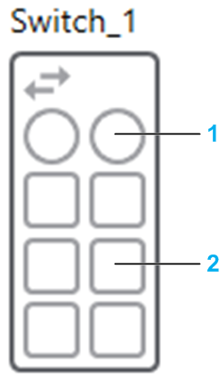
| Item | Description |
| 1 | Fiber optic connectors are represented by a circle. |
| 2 | RJ45 connectors are represented by a square. |
Ports of Modules of PACs
The following figure shows an example of a local rack containing a CPU and a communication module.
| Item | Description |
| 1 | Service port |
| 2 | shown disabled |
| 3 |
|
The backplane port is not shown.
Ports of Communication Cards
Ports of the following cards are managed separately from the device:
Network interface cards (NICs)
Communication cards of Altivar Process devices
The following figure shows an example of the representation of ports of the NICs of a device representing a workstation.
| Item | Description |
| 1 | Areas in which Ethernet communication ports can be shown depending on the configuration of the device. |
| 2 | Port 1 of NIC1. |
| 3 | Redundant port 2 of NIC1. |
| 4 | Port 1 of NIC2 (non-redundant) |
The following figure shows an example of the representation of ports of a device representing an ATV6xx device.
| Item | Description |
| 1 | Embedded port 1. |
| 2 | Ports of devices that use non-Ethernet communication protocols are not shown. |
| 3 | Port 1 of the communication card when the card is present. |
| 4 | Port 2 of the communication card. |