

Overview
The node shows the devices that your system project contains. Their location depends on how you create the devices.
You can view and configure properties of each device by selecting it and opening a context menu. You can also export and import devices.
The node lets you organize the topology by creating a folder structure. You can change the order in which folders and devices are displayed by dragging an object to its new position within the node, the same folder, or to a different folder.
Node Description
The following figure shows a partial view of the pane with examples of various objects that the node contains.
Item |
Description |
|---|---|
1 |
node (root folder). By default, each device that you add directly from the catalog to a physical view is assigned to it. Right-click it to open a context menu. |
2 |
User-generated folder. |
3 |
Device with module (for example, a communication card) assigned to a user-generated folder. The device and child elements are shown with a lock and their name appears in italic when the device is locked. |
4 |
PROFIBUS remote master (PRM) gateway device. |
5 |
PROFIBUS slave devices. |
68 |
PROFIBUS-to-INTERBUS gateway. |
7 |
Slave devices of the PROFIBUS-to-INTERBUS gateway. |
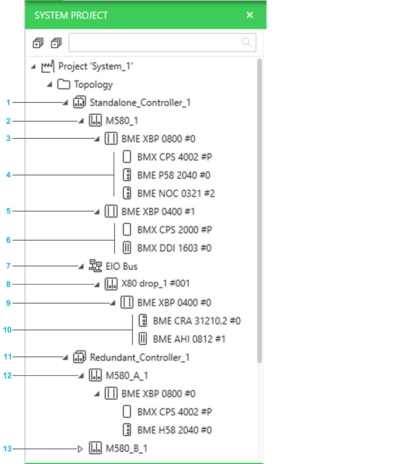
The following figure shows a partial view of the pane with examples of M580 PACs that have been added.
Item |
Description |
|---|---|
1 |
Object representing the standalone PAC as a whole. The node is created with its default configuration when you add it to the system project. Changes that you make to the hardware configuration of the PAC by editing the control project are reflected in this pane. NOTE: For non-M580 controllers, no child elements are shown.
|
2 |
Local rack. Racks and modules are shown with a lock and their name appears in italic when the PAC is locked. |
3 |
Backplane of the main local rack. The name of a backplane is followed by its address in the rack. |
4 |
Modules of the main local rack. The name of a module is followed by its position (address) on the backplane. |
5 |
Backplane of the extended local rack. |
6 |
Modules of the extended local rack. |
7 |
EIO bus that is shown only when you add a drop. |
8 |
Remote rack (drop). The name of the drop is followed by the values of the rotary switches of its CRA adapter module. NOTE: The address of the drop on
the bus is indicated by the attribute of its CRA adapter module when you select it in the Communication Mapping View.
|
9 |
Backplane of the main remote rack. |
10 |
Modules of the main remote rack. |
11 |
Object representing the redundant PAC as a whole. |
12 |
Local rack with role A. You can change the hardware configuration by editing the control project of either local rack. Changes are reflected in both racks. |
13 |
Local rack with role B. |
Devices Locked for Editing
A device and its child elements are shown with a lock and their name appears in italic when they are locked because you have opened an associated object in an editor. For example, you are editing the control project of a PAC, the fieldbus of a gateway device, or have opened a DTM.
Once the object editor is closed, the representation of the node returns to normal and is updated (if applicable).
Selecting Multiple Folders and/or Devices
You can select a combination of folders and devices, including PACs that appear in the folder structure. However, your selection cannot contain individual modules of a device (for example, only the rack or a communication module of a PAC or only the communication card of a drive). That is, nodes need to be collapsed.
Moving Devices to Another Topological Folder
You can change the location of devices inside the folder structure of the topology by selecting one or more devices and dragging them onto another existing topological folder:
If the target folder is expanded, you can select the position of the device among existing devices.
If the target folder is collapsed, the device is added in last position. Holding over a collapsed folder expands it.
For PACs and other devices with child elements (such as gateways), you cannot move child elements individually (for example, the communication module of a rack or a PROFIBUS slave device).
Node Actions
The table describes the commands of the context menu of the node.
Command |
Description |
|---|---|
|
Creates a new folder with properties set to default values. |
|
Pastes the objects that have been added to the Clipboard from the pane. For details, refer to the topic describing the paste action for folders or devices. |
|
Opens the window, which lets you export to file the complete topology of the system project, a selection of devices, or a single one. You can also export the corresponding physical views and physical links. |
|
Opens the dialog box, which lets you select a topology export file (.xpt) that has been created by using the command. It lets you import the objects contained in the file. |
Topology Folder Actions
The table describes the commands of the context menu of the root folder or topological folders.
Command |
Description |
|---|---|
|
Creates a new folder with properties set to default values. |
|
Adds the folder, any subfolders, and devices that it contains to the Clipboard, and removes it from the system project. You can use the command when multiple objects are selected. |
|
Adds the folder, any subfolders, and devices that it contains to the Clipboard. You can use the command when multiple objects are selected. NOTE: You cannot copy from the root folder.
|
|
Refer to the description of the command in the topic describing node actions. |
|
|
|
|
|
Deletes the folder after confirming the command. Deleting a folder also deletes the devices contained in the folder and all subfolders. You can use the command when multiple objects are selected. NOTE: You cannot
delete the root folder.
|
Device Actions
The table describes the commands of the context menu of a device that are specific to the pane. For a description of the other commands, refer to the topic describing the device context menu.
Command |
Description |
|---|---|
|
Adds the device, its child elements (for example, slave devices for a gateway), and configuration files to the Clipboard and removes them from the system project. For devices with child elements (such as gateways), the child elements are cut. You can use the command when multiple objects are selected. |
|
Adds the device, its child elements (for example, slave devices for a gateway), and configuration files to the Clipboard. You can use the command when multiple objects are selected. |
|
Opens the window, which lets you export to file the device or a selection of devices. You can also export the corresponding physical views and physical links. |