|
Mapping Data Attributes to PLC Memory
|
|


|
(Original Document)
|
|
Mapping Data Attributes to PLC Memory
|
|
|
(Original Document)
|
|
FC
|
Server
|
Client
|
Description
|
|---|---|---|---|
|
BR
|
–
|
√
|
Buffered report control block
|
|
CF
|
√
|
√
|
Configuration value
|
|
CO
|
√
|
√
|
Process control service command or status
|
|
DC
|
–
|
–
|
Description attribute
|
|
GO
|
–
|
√
|
GOOSE report control block
|
|
MX
|
√
|
√
|
Process measurement value
|
|
RP
|
–
|
√
|
Unbuffered report control block
|
|
SP
|
√
|
√
|
Process set point to support reading of status
|
|
ST
|
√
|
√
|
Process status value
|
|
√ The FC is supported.
– The FC is not supported.
|
|||
|
Step
|
Action
|
|---|---|
|
1
|
In the I/O Mapping window, select either:
|
|
2
|
Click the System tab.
The mapping table displays system data items for the module in its role as server or client.
|
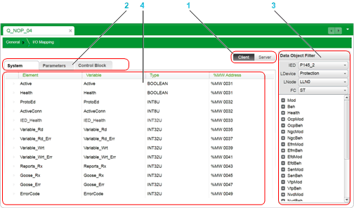
1Client / Server selector buttons
2Data items selector tabs
3Data Object / Data Attribute Filter
4Mapping table
1Client / Server selector buttons
2Data items selector tabs
3Data Object / Data Attribute Filter
4Mapping table
|
Step
|
Action
|
|---|---|
|
1
|
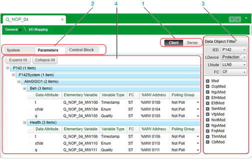
In the I/O Mapping window, select either:
|
|
2
|
Click the Parameters tab.
The Data Object Filter presents data objects associated with the selected tab.
|
|
3
|
In the Data Object Filter, make the following selections:
The Data Object Filter displays the associated data objects and data attributes.
|
|
4
|
Select a data object or data attribute in the Data Object Filter, and then drag it to the mapping table in the Parameters tab. If you selected a:
NOTE: The data object order of data mapping depends on the structure defined in the data model. |
|
5
|
If you selected Client in step 1, expand the mapping table to display each data attribute, then edit the Polling Group setting for the attribute. Settings include:
|
|
6
|
Repeat steps 2...5 for each data object or data attribute you want to add to map to a located memory address in the PLC.
|
|
7
|
Save your edits.
|
|
Step
|
Action
|
|---|---|
|
1
|
In the I/O Mapping window, click Client.
The Data Object Filter presents the IEDs associated with the module in its role as IEC61850 client.
|
|
2
|
In the I/O Mapping window, click Control Block.
The Data Object Filter presents data objects associated with the selected tab.
|
|
3
|
In the Data Object Filter, drill down to the data attributes you want to add, by making the following selections:
The Data Object Filter displays the associated data objects and data attributes.
|
|
4
|
Select a item in the Data Object Filter, and then drag it to the mapping table in the selected tab.
|
|
5
|
Repeat steps 2...4 for each data item you want to add to map to a located memory address in the PLC.
|
|
6
|
Save your edits.
|
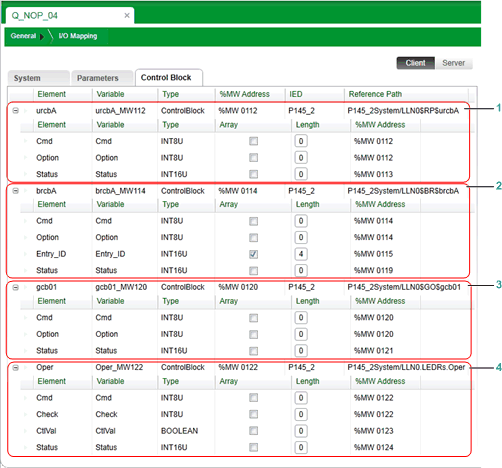
1Unbuffered report control block (RP)
2Buffered report control block (BR)
3GOOSE report control block (GO)
4Process control value service block (CO)
|
Step
|
Action
|
|---|---|
|
1
|
In the mapping table, select an item you want to delete.
|
|
2
|
Click the right mouse button to open a context menu.
|
|
3
|
Click Delete to remove the selected data items from the mapping table.
|
|
4
|
Repeat steps 1...3 for each item you want to delete.
|
|
5
|
Save your edits.
|
