|
Rules for Interconnectivity
|
|
|
|
|
140NOC78100 Module Interconnectivity
|
Network Type
|
Description
|
|---|---|---|
|
the 140NOC78100 module interlinked with the 140CRP31200 module
|
|
provides network transparency between the control network and the remote I/O network, while preserving network determinism
|
|
the 140NOC78100 module interlinked with up to three 140NOC78000 modules and the 140CRP31200 module
|
|
provides network transparency between the control network and the device network, while preserving network determinism
|
|
one 140NOC78000 modules interlinked with the service/extend port of the 140NOC78100 module
NOTE: If you to install up to three 140NOC78000 modules, please refer to the Quantum EIO System Planning Guide for bandwidth guidelines. |
|
provides network transparency between the control network and the extended distributed I/O network
|
|
the 140NOC78100 module interlinked with up to three 140NOC78000 modules
|
provides network transparency between the control network and up to 3 independent distributed I/O networks
|
|
Step
|
Action
|
|---|---|
|
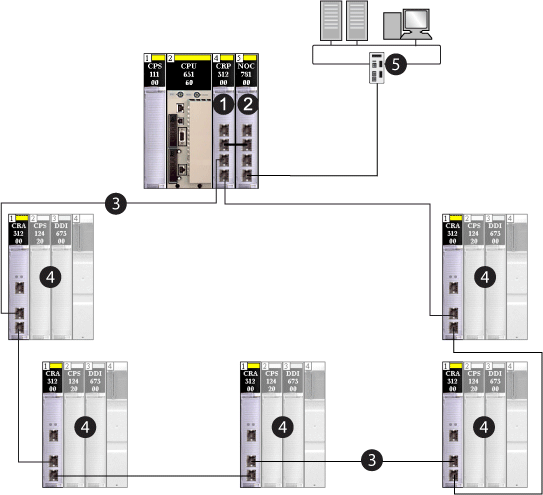
1
|
Install one 140CRP31200 remote I/O head module and one 140NOC78100 control head module on the local rack.
|
|
2
|
Connect the interlink port (ETH 2) of the 140NOC78100 module to the interlink port (ETH 2) of the 140CRP31200 module to provide network transparency between the control network and the Ethernet remote I/O network.
|
|
3
|
Connect the start of the main ring to the device network port (ETH 3 or ETH 4) of the 140CRP31200 module.
|
|
4
|
Connect the end of the main ring to the device network port (ETH 3 or ETH 4) of the 140CRP31200 module.
|
|
5
|
Connect the control network port (ETH 3 or ETH 4) of the 140NOC78100 module to the control network.
|

1140CRP31200 remote I/O head module
2140NOC78100 control head module interlinked with the 140CRP31200 module on the local rack
3main ring
4Ethernet remote I/O drops on the main ring
5control network
|
Step
|
Action
|
|---|---|
|
1
|
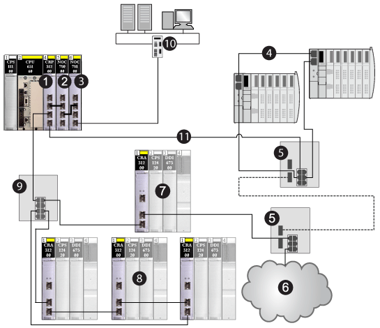
Install one 140CRP31200 remote I/O head module, up to three 140NOC78000 distributed I/O head modules (that can be interlinked with the 140CRP31200 module), one 140NOC78100 control head module on the local rack, and an additional 140NOC78000 module (that can be interlinked with the 140NOC78100 module).
|
|
2
|
Connect the interlink port (ETH 2) of the 140NOC78000 module to the interlink port (ETH 2) of the 140CRP31200 module.
|
|
3
|
Connect the interlink port (ETH 2) of the 140NOC78100 module to the device network/interlink port (ETH 3) of the 140NOC78000 module.
|
|
4
|
Connect the start of the main ring to the device network port (ETH 3 or ETH 4) of the 140CRP31200 module.
|
|
5
|
Connect the end of the main ring to the device network port (ETH 3 or ETH 4) of the 140CRP31200 module.
|
|
6
|
Refer to the Predefined Configuration Files topic in the Quantum EIO System Planning Guide for details on installing DRSs and distributed I/O devices.
|
|
7
|
Connect the control network port (ETH 3 or ETH 4) of the 140NOC78100 module to the control network.
|

1140CRP31200 remote I/O head module
2140NOC78000 distributed I/O head module (interlinked with the 140CRP31200 module to support the device network)
3140NOC78100 control head module (interlinked with the 140NOC78000 module to provide network transparency between the control network and the device network)
4distributed I/O sub-ring
5DRSs with a predefined configuration file to support copper-to-fiber and fiber-to-copper transitions on the main ring
6distributed I/O cloud
7remote I/O drop on the main ring
8remote I/O drops on a remote I/O sub-ring
9DRS connecting the remote I/O sub-ring to the main ring
10control network
11main ring
|
Step
|
Action
|
|---|---|
|
1
|
Install one 140CRP31200 remote I/O head module, up to three 140NOC78000 distributed I/O head modules (that can be interlinked with the 140CRP31200 module), one 140NOC78100 control head module on the local rack, and an additional 140NOC78000 (that can be interlinked with the 140NOC78100 module).
|
|
2
|
Connect the interlink port (ETH 2) of the 140NOC78000 module to the interlink port (ETH 2) of the 140CRP31200 module.
|
|
3
|
Connect the device network/interlink port (ETH 3) of the 140NOC78000 module to the service/extend port (ETH 1) of the 140NOC78100 module.
|
|
4
|
Connect the device network port (ETH 4) of the 140NOC78000 to your existing distributed I/O network.
|
|
5
|
Connect the control network port (ETH 3 or ETH 4) of the 140NOC78100 module to the control network.
|
|
6
|
Connect the start of the main ring to the device network port (ETH 3 or ETH 4) of the 140CRP31200 module.
|
|
7
|
Connect the end of the main ring to the device network port (ETH 3 or ETH 4) of the 140CRP31200 module.
|
|
8
|
Refer to the Predefined Configuration Files topic in the Quantum EIO System Planning Guide for details on installing DRSs and distributed I/O devices.
|

1140CRP31200 remote I/O head module
2140NOC78000 distributed I/O head module (interlinked with the extend port of the 140NOC78100 module to support the extended distributed I/O network and also interlinked with the 140CRP31200 module to support the device network)
3140NOC78100 control head module (interlinked with the 140NOC78000 module (2) to provide network transparency between the device network and the control network)
4extended distributed I/O network
5distributed I/O sub-ring
6DRSs with a predefined configuration file to support copper-to-fiber and fiber-to-copper transitions on the main ring
7distributed I/O cloud
8remote I/O drop on the main ring
9remote I/O drops on the remote I/O sub-ring
10DRS connecting the remote I/O sub-ring to the main ring
11control network
|
Step
|
Action
|
|---|---|
|
1
|
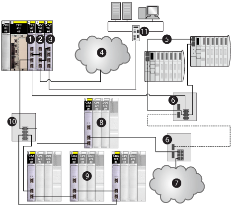
Install one 140CRP31200 remote I/O head module, up to three 140NOC78000 distributed I/O head modules (that can be interlinked with the 140CRP31200 module), one 140NOC78100 control head module on the local rack and an additional 140NOC78000 module (that can be interlinked with the 140NOC78100 module).
|
|
2
|
Connect the interlink port (ETH 2) of the 140CRP31200 module to the interlink port (ETH 2) of the 140NOC78000 module.
|
|
3
|
Connect the interlink port (ETH 2) of a second 140NOC78000 module to the interlink port (ETH 2) of the 140NOC78100 module.
|
|
4
|
Connect the device network port (ETH 4) of the 140NOC78000 to your existing distributed I/O network.
|
|
5
|
Connect the control network port (ETH 3 or ETH 4) of the 140NOC78100 module to the control network
|
|
6
|
Connect the start of the main ring to the device network port (ETH 3 or ETH 4) of the 140CRP31200 module.
|
|
7
|
Connect the end of the main ring to the device network port (ETH 3 or ETH 4) of the 140CRP31200 module.
|
|
8
|
Refer to the Predefined Configuration Files topic in the Quantum EIO System Planning Guide for details on installing DRSs and distributed I/O devices.
|

1140CRP31200 remote I/O head module
2140NOC78000 distributed I/O head module (interlinked with the 140CRP31200 module
3140NOC78100 control head module
4140NOC78000 distributed I/O head module (interlinked with the 140NOC78100 module to provide network transparency between the independent distributed I/O network and the control network)
5independent distributed I/O network (participates only in the control network portion of a Quantum EIO system)
6distributed I/O sub-ring
7DRSs with a predefined configuration file to support copper-to-fiber and fiber-to-copper transitions on the main ring
8distributed I/O cloud
9remote I/O drop on the main ring
10remote I/O drops on the remote I/O sub-ring
11DRS connecting the remote I/O sub-ring to the main ring
12control network