|
|
|
|
Step
|
Action
|
|---|---|
|
1
|
Install a 140NOC78100 control head module on the local rack. Install a 140CRP31200 remote I/O head module and 140NOC78000 distributed I/O head modules (the number of which depends upon your desired network) on the local rack.
|
|
2
|
NOTE: Use copper shielded twisted 4-pair CAT5e (10/100 Mbps) cable to interlink the head modules on the local rack. |
|
3
|
Install an Ethernet switch on the control network a distance equal to or less than 100 m from the 140NOC78100 module on the local rack.
NOTE: The switch does not have to be a managed dual-ring switch (DRS). |
|
4
|
Connect the control network port (ETH 3 or ETH 4) of the 140NOC78100 module — using copper shielded CAT6 (10/100/1000 Mbps — to an Ethernet port on the switch located on the control network.
|

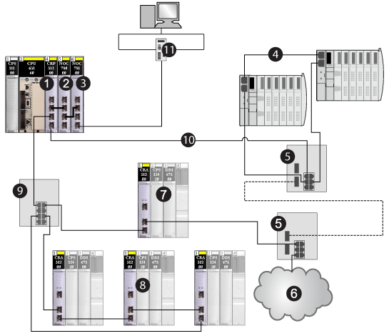
1140CRP31200 remote I/O head module
2140NOC78000 distributed I/O head module (interlinked with the 140CRP31200 module to support the device network)
3140NOC78100 control head module (interlinked with the 140NOC78000 module to provide network transparency between the control network and the device network)
4distributed I/O sub-ring
5DRSs with a predefined configuration file to support copper-to-fiber and fiber-to-copper transitions on the main ring
6distributed I/O cloud
7remote I/O drop on the main ring
8remote I/O drops on a remote I/O sub-ring
9DRS connecting the remote I/O sub-ring to the main ring
10main ring
11control network
|
Step
|
Action
|
|---|---|
|
1
|
Install a 140NOC78100 control head module on the local rack. Install a 140CRP31200 remote I/O head module and 140NOC78000 distributed I/O head modules (the number of which depends upon your desired network) on the local rack.
|
|
2
|
NOTE: Use copper shielded twisted 4-pair CAT5e (10/100/1000 Mbps) cable to interlink the head modules on the local rack. |
|
3
|
Install and connect 2 Ethernet managed dual-ring switches (DRSs via copper shielded twisted 4-pair CAT5e (10/100 Mbps) cable on the control network a distance equal to or less than 100 m from each other and from the 140NOC78100 module on the local rack.
|
|
4
|
|

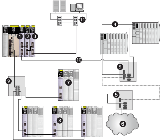
1140CRP31200 remote I/O head module
2140NOC78000 distributed I/O head module (interlinked with the 140CRP31200 module to support the device network)
3140NOC78100 control head module (interlinked with the 140NOC78000 module to provide network transparency between the control network and the device network)
4distributed I/O sub-ring
5DRSs with a predefined configuration file to support copper-to-fiber and fiber-to-copper transitions on the main ring
6distributed I/O cloud
7remote I/O drop on the main ring
8remote I/O drops on a remote I/O sub-ring
9DRS connecting the remote I/O sub-ring to the main ring
10main ring
11control network with 2 DRSs that provide redundancy