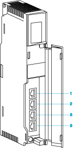
The 140NOC78100 control head module is mainly responsible for providing network transparency between devices located on a (including and/or ), an , and a , while preserving for remote I/O devices on the device network.
The 140NOC78100 module also:
-
operates in a redundant network that uses the RSTP protocol
-
configures IP parameters and device configuration files for I/O devices
-
supports functionality
-
operates with other Quantum EIO head modules (140CRP31200, 140NOC78000) or operates without being interlinked with these head modules on the
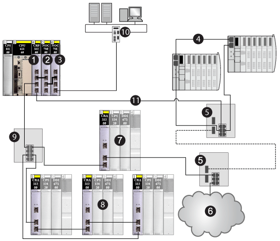
The following graphic shows a control network [10] connected to a Quantum EIO system via interlink of the 140NOC78100 control head module with the 140NOC78000 distributed I/O head module and the 140CRP31200 remote I/O head module on the local rack. The 140NOC78100 module provides network transparency between the control network and the device network.
1
140CRP31200 remote I/O head module
2
140NOC78000 distributed I/O head module interlinked with the 140CRP31200 module
3
140NOC78100 control head module interlinked with the 140NOC78000 module on the local rack
4
distributed I/O sub-ring
5
dual-ring switch (DRS) configured for copper-to-fiber and fiber-to-copper transition on the main ring (connecting the distributed I/O sub-ring and the distributed I/O cloud to the main ring)
6
distributed I/O cloud
7
remote I/O drop on the main ring
8
remote I/O drops on the remote I/O sub-ring
9
DRS on the main ring (connecting the remote I/O sub-ring to the main ring)
10
control network (connected by the 140NOC78100 module)
11
main ring
What Comprises a Network?
-
IP addresses are within one subnet.
-
Devices communicate to each other directly.
-
Target addresses outside of the subnet are directed to a router.
How Does Routing Work Between Networks?
Routers subdivide large networks into smaller networks and subnetworks. The netmask assigns the IP address of the individual devices to a particular subnetwork.
The division into subnetworks with the aid of the netmask is performed in much the same way as the division of the network addresses (net id) into classes A to C.
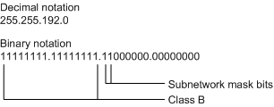
The bits of the host address (host ID) that represent the mask are set to 1. The remaining bits of the host address in the netmask are set to 0 (see the following examples).
Example of a netmask:
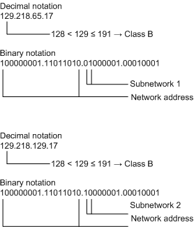
Example of IP address with subnetwork assignment when the above subnet mask is applied:
Example of how the network mask is used:
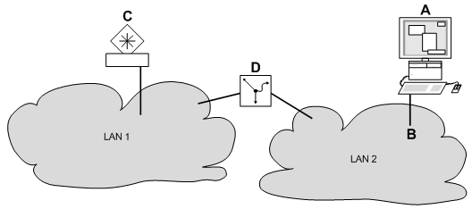
In a large network, it is possible that routers separate the fieldbus network from the extended network. How does addressing work in such a case?
A
control network
B
fieldbus network
C
extended network
D
router
The control network (A) wants to send data to the extended network (C). A knows C’s IP address and also knows that the router (D) knows the way to C from the fieldbus network (B).
A, therefore, puts its message in an envelope and writes C’s IP address as the destination address. For the source address, A writes its own IP address on the envelope.
A then places this envelope in a second one with D’s MAC address as the destination and its own MAC address as the source. This process is comparable to going from layer 3 to layer 2 of the ISO/OSI base reference model.
Finally, A puts the entire packet into the mailbox. This is comparable to going from layer 2 to layer 1, i.e., to sending the data packet over the Ethernet.
D receives the letter and removes the outer envelope. From the inner envelope, it recognizes that the letter is meant for C. D places the inner envelope in a new outer envelope and searches its address list (the ARP table) for C’s MAC address. D writes C’s MAC address on the outer envelope as the destination address and its own MAC address as the source address. D then places the entire data packet in the mail box.
C receives the letter and removes the outer envelope, and finds the inner envelope with A’s IP address. Opening the inner envelope and reading its contents corresponds to transferring the message to the higher protocol layers of the ISO/OSI layer model.
C would now like to send a reply to A. C places its reply in an envelope with A’s IP address as destination and its own IP address as source. But where does C send the answer because it did not receive A’s MAC address, which was lost when D replaced the outer envelope.
In the MIB, C finds D listed under the variable hmNetGateway-IPAddr as a means of communicating with A. C therefore puts the envelope with the IP addresses in a further envelope with D’s MAC destination address.
The letter now travels back to A via D, the same way the first letter traveled from A to C.
The following table details the steps in the Control Expert DTM:
|
Step
|
Action
|
|
1
|
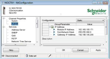
Double-click the 140NOC78100 module in the DTM Browser. Select TCP/IP in the Channel Properties list, and set the 140NOC78100 module’s control network address and control network gateway.
Click Apply to save changes, or click OK to save changes and close the window.
|
|
2
|
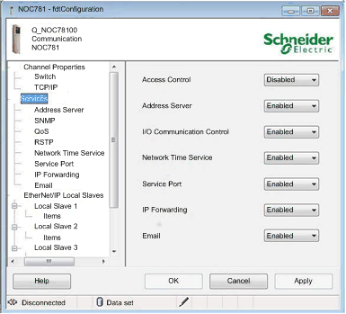
Select Services to view the Ethernet services that you can enable or disable. In the right pane, select Enabled for the IP Forwarding service.
Click Apply to save changes, or click OK to save changes and close the window.
|
|
3
|
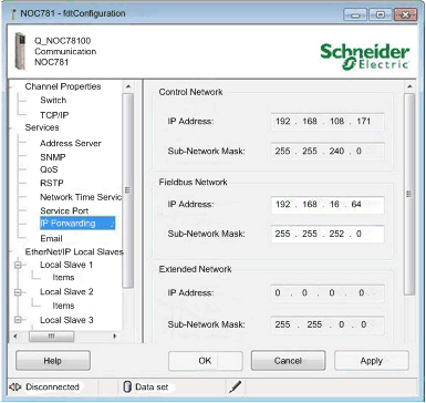
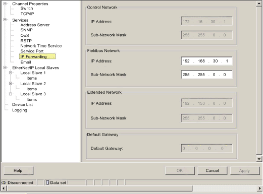
Select IP Forwarding in the Services list to access the IP forwarding service parameters. Set the IP Address and the Sub-Network Mask for the Control Network, the Fieldbus Network, and the Extended Network.
Click Apply to save changes, or click OK to save changes and close the window.
|
|
4
|
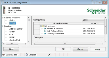
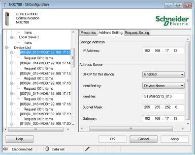
Double-click the 140NOC78000 module in the DTM Browser. Select TCP/IP in the Channel Properties list, and set the 140NOC78000 module’s fieldbus address and gateway address.
Click Apply to save changes, or click OK to save changes and close the window.
|
|
5
|
Confirm that all fieldbus devices are set with the proper gateway address.
NOTE: If they are defined via DHCP from the 140NOC78000 module, cycle power the devices to configure the new gateway address. If they are defined in the device or from an external address server, reconfigure the gateway address as required by the device.
Click Apply to save changes, or click OK to save changes and close the window.
|
|
6
|
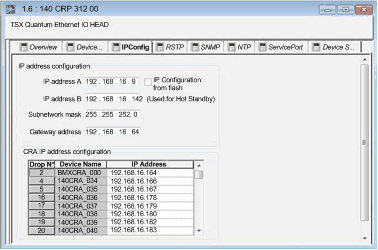
Double-click the 140CRP31200 module on the local rack. Select the IPConfig tab and confirm that the fieldbus address and gateway address are set. When the system starts, the EIO drops are provided new addresses.
NOTE: If previously configured, cycle power the distributed I/O devices to reconfigure with the new gateway address.
|
|
7
|
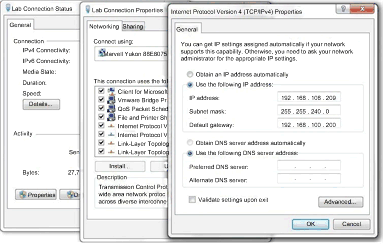
Confirm that the PCs on the control network are set with a proper IP address and subnet mask to access the 140NOC78100 module’s IP forwarding service.
|
|
8
|
Finally, to access devices on the fieldbus network, add a routing entry in the PC’s routing table to define the 140NOC78100 module as the default gateway to the fieldbus network.
|
Multiple Ethernet Cards in a PC
A PC Ethernet card connected to a network on the 140NOC78100 module can communicate with devices within that subnet. To communicate with devices on the other two 140NOC78100 networks, set the 140NOC78100 module’s IP address as the Ethernet card’s default gateway.
If you have more than one Ethernet card installed in the PC (each with a configured IP address on a particular subnet and a configured default gateway) and you try to communicate with a device that is not on the 140NOC78100 module network (or any network not assigned to the Ethernet cards in the PC), the application does not know what default gateway on which Ethernet card to use.
To fix this, add a static route to your PC for each of the other 140NOC78100 module networks that you want to access from the 140NOC78100 module network to which you are connected. Use the route -p to create a persistent route across system boots.
Example:
c:\Route ADD 192.153.0.0 mask 255.255.0.0 172.16.30.1
c:\Route ADD 192.168.0.0 mask 255.255.0.0 172.16.30.1
Where:
192.153.0.0 is the extended network in our example.
192.168.0.0 is the distributed I/O network in our example.
172.16.30.1 is the IP address of the 140 NOC 781 00 module on the control network.
NOTE: Do not use multiple default routes.
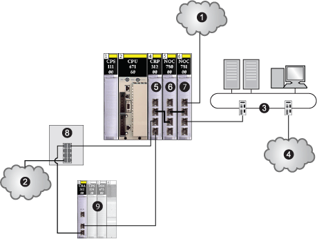
The following figure shows the IP forwarding service configuration in the 140NOC78100 module for the previous example.
How is the 140NOC78100 Module’s Default Gateway Used?
As previously stated, if a datagram is targeted outside of a network, the datagram is sent to the default gateway. In a Quantum EIO system, the default gateway is the 140NOC78100 module. If the datagram is not targeted to a device in one of the 3 networks known by the 140NOC78100 module, the datagram is sent to the 140NOC78100 module’s default gateway. In this example, the default gateway is a router further up in the Ethernet infrastructure.
1
extended network (example: 192.153.x.x)
2
distributed I/O network (example: 192.168.x.x)
3
control network (example: 172.16.x.x)
1
extended network (example: 192.153.x.x)
2
distributed I/O network (example: 192.168.x.x)
3
control network (example: 172.16.x.x)
4
router to other networks (example: 131.158.x.x)
5
140CRP31200 remote I/O head module
6
140NOC78000 distributed I/O head module
7
140NOC78100 control head module
8
dual-ring switch (DRS) on main ring connected to distributed I/O network and remote I/O sub-ring
9
remote I/O sub-ring 