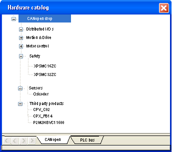
The devices which can be configured using Control†Expert are shown in the Hardware Catalog:
To configure a slave, perform the following actions:
|
Step
|
Action
|
|
1
|
Access the CANopen bus configuration screen. |
|
2
|
Double-click on the slave to be configured.
|
|
3
|
Configure the usage function using the Config tab.
|
|
4
|
Configure the PDOs using the PDO tab.
|
|
5
|
Select the error control using the Error control tab.
|
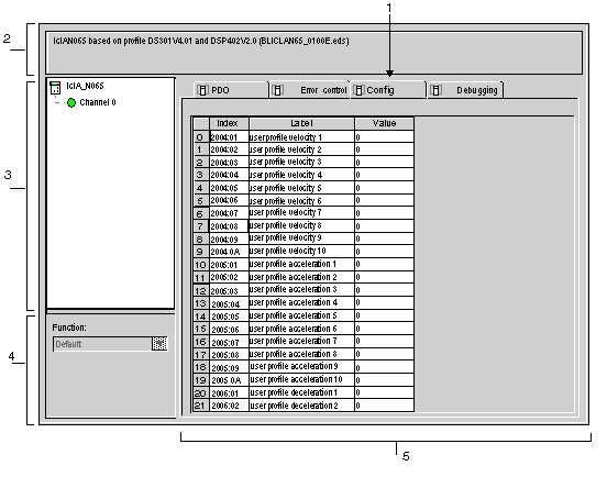
The following figure shows an example of the configuration screen of a slave:
The next table shows the various elements of the configuration screen and their functions:
|
Number
|
Element
|
Function
|
|
1
|
Tabs
|
The tab in the foreground indicates the type of screen displayed. In this case, it is the configuration screen.
|
|
2
|
Module area
|
Gives a reminder of the deviceís shortened name.
|
|
3
|
Channel area
|
This zone allows you to select the communication channel to be configured.
By clicking on the device, you display the following tabs:
-
Description†: gives the characteristics of the device,
-
CANopen: allows you to access SDO (in online mode),
-
I/O Objects: allows pre-symbolizing of the input/output objects,
-
Fault: accessible in online mode only.
By clicking on the channel, you display the following tabs:
-
PDO(input/output objects)
-
Error control,
-
Configuration.
-
Debug which can be accessed only in online mode.
-
Diagnostics, accessible only in Online mode.
|
|
4
|
General parameters area
|
This field allows you to select the slave function.
|
|
5
|
Configuration area
|
This area is used to set up the channels of the devices.
Some devices can be configured with an external tool. In this case, the configuration is stored in the device and you cannot enter configuration parameters because this field is empty.
|
NOTE: Refer to the documentation of each device for information on general, configuration, adjustment and debugging parameters.
NOTE: All parameters are not sent when the device takes its configuration. The CPU send only parameters which are different from the default values.
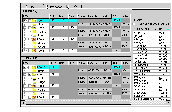
PDOs make it possible to manage the communication flow between the CANopen Master and the slaves. The PDO tab allows to configure a PDO.
This screen is divided into 3 parts:
-
Transmit PDOs: information transmitted by the Slave to the Master,
-
Receive PDOs: information received by the Slave from the Master,
-
Variables: variables that can be mapped to the PDOs. To assign a variable to a PDO, drag and drop the variable into the desired PDO. No variable can be assigned with a static PDO.
NOTE: To configure the STB NCO 1010, itís necessary to determine all the objects that are valid for this device and to configure them manually in the PDOs.
For more information about the list of the associated objects, please refer to the STB user manual.
For more information about the use of the PDOs, see [...].
The Error control tab for CANopen slave modules allows you to configure monitoring.
Two choices are possible:
-
Heartbeat: The Heartbeat mechanism consists of sending cyclical presence messages generated by a Heartbeat Producer. A Heartbeat transmitter (producer) sends messages recurringly. The sending time is configured with the Node Heartbeat Procucer Time Value. One or several elements connected to the network receive this message. The Heartbeat consumer surveys the Heartbeat message reception. The default value of consumer time is set to (1.5 * Producer Heartbeat Time). If its duration exceeds the Heartbeat Consumer Time (1.5 * Producer Heartbeat Time), an Hearbeat event is created and the device is in default.
If a M340 Master PLC is used on the CANopen bus, all the nodes using the Heartbeat control mode are producers. The master surveys the transmission and the reception of the messages and it is the only receiver of the Heartbeat messages sent by the nodes.
Control†Expert supports devices that are only heartbeat producer (no consumer) and does not support the node guarding. In this case, the value of node heartbeat consumer time is set to 0. This value is displayed on the error control tab of the device.
The Master can send Heartbeat messages to the slaves. The Master Heartbeat producer time is set at 200†ms and is not modifiable.
-
Node guarding: Node Guarding is the monitoring of network nodes. The NMT (Network Management) master sends an RTR (Remote Transmission Request) at regular intervals (this period is called Guard Time) and the concerned node must answer in a given time lapse (the Node Life Time equals the Guard Time multiplied by the Life Time Factor).
The Life Time value is set at 2 and is not modifiable.
NOTE: Some devices only support Heartbeat or Node Guarding. For devices which support Heartbeat and Node Guarding, the only choice in Control†Expert is the Heartbeat mechanism.


