|
|
(Original Document)
|
|
Step
|
Action
|
|---|---|
|
1
|
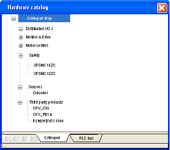
Access the CANopen bus configuration screen.
|
|
2
|
Double-click on the slave to be configured.
|
|
3
|
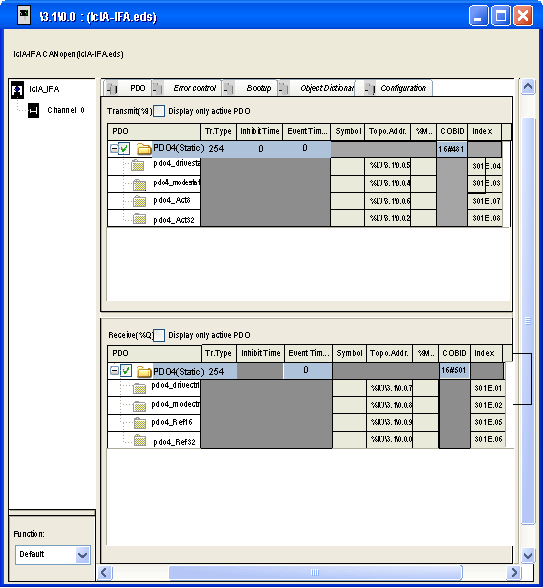
Configure the Bootup Procedure using the Bootup tab.
|
|
4
|
Integrate a third pary product using the Object Dictionary tab.
|
|
5
|
Configure the usage function using the Config tab.
|
|
6
|
Configure the PDOs using the PDO tab.
|
|
7
|
Select the error control using the Error control tab.
|
|
Number
|
Element
|
Function
|
|---|---|---|
|
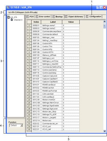
1
|
Tabs
|
The tab in the foreground indicates the type of screen displayed. In this case, it is the configuration screen.
|
|
2
|
Module area
|
Gives a reminder of the deviceís shortened name.
|
|
3
|
Channel area
|
This zone allows you to select the communication channel to be configured.
By clicking on the device, you display the following tabs:
By clicking on the channel, you display the following tabs:
|
|
4
|
General parameters area
|
This field allows you to select the slave function.
|
|
5
|
Configuration area
|
This area is used to set up the channels of the devices.
Some devices can be configured with an external tool. In this case, the configuration is stored in the device and you cannot enter configuration parameters because this field is empty.
|

 WARNING WARNING |
|
UNEXPECTED EQUIPMENT OPERATION
Manually verify all deactivated standard checks on the device before operating the system.
Changing the default parameters of the Bootup tab will bypass standard system checks.
Failure to follow these instructions can result in death, serious injury, or equipment damage.
|
 WARNING WARNING |
|
UNEXPECTED EQUIPMENT OPERATION
Manually verify all Object Dictionary values.
Changing the default values of the Object Dictionary table will generate non-standard behaviour of the equipment.
Failure to follow these instructions can result in death, serious injury, or equipment damage.
|
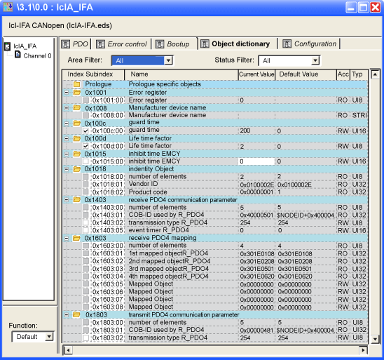
|
Area Filter
|
|
|
All
|
show all area.
|
|
Prologue/ Epilogue
|
show only prologue and epilogue projects
|
|
[XXXX...YYYY]
|
show only objects between XXXX to YYYY
|
|
Status filter
|
|
|
All
|
show all objects
|
|
Configured
|
show only transmitted objects to the device during boot up
|
|
Not Configured
|
show only not transmitted objects to the device
|
|
Modified
|
show only objects from which values are different from default values
|
|
Right click on an object in the prologue and epilogue sections
|
|
|
Cut
|
Cut the row and copy the object in the clipboard
|
|
Copy
|
Copy the object in the clipboard
|
|
Paste
|
Paste the object in the selected row
|
|
Delete
|
Delete the selected object
|
|
Move up
|
Used to manage the order fo the list
|
|
Move down
|
Used to manage the order fo the list
|
|
Configured
|
If checked, the object is transmitted to the device
|
|
Expand all
|
Expand all nodes of the tree
|
|
Collapse all
|
Collapse all nodes of the tree
|
|
Right click on an object in the standard sections
|
|
|
Copy
|
Copy the object on the clipboard
|
|
Configured
|
If checked, the object is transmitted to the device
|
|
Expand all
|
Expand all nodes of the tree
|
|
Collapse all
|
Collapse all nodes of the tree
|