|
Configuration of the equipment
|
|
|
(Original Document)
|
|
Step
|
Action
|
|---|---|
|
1
|
In the Project browser, double-click on Configuration then 3:†CANopen.
|
|
2
|
In the CANopen window, double-click on the Lexium representation. The Lexium configuration window opens.
|
|
3
|
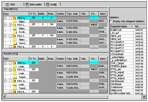
Click on the PDO tab to see the PDO configuration, the variables and their topological addresses.
|
|
4
|
For this example, select PDO2(Static) in the Transmit (%I) and the Received (%Q) windows.
 |
|
5
|
Click on the Error control tab and set the Node Heartbeat producer time to 300ms
|
|
6
|
Click on the
 button in the toolbar to validate the configuration. button in the toolbar to validate the configuration. |
|
7
|
Close the window.
|
|
Step
|
Action
|
|---|---|
|
1
|
In the Project browser, double-click on Configuration then 3:†CANopen.
|
|
2
|
In the CANopen window, double-click on the Advantys STB representation. The STB NCO2212 configuration window opens.
|
|
3
|
In Function zone, select Autoconf.
 In this example, we use the Autoconf function because autoconfigurable modules are inserted on the STB island.
|
|
4
|
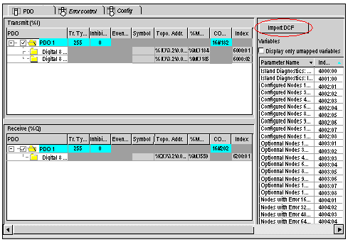
Click on the PDO tab to see the PDO configuration, the variables and their topological addresses. Click on the right button of the horizontal scroll bar to see the Import DCF button.
|
|
5
|
Click on Import DCF button to load the DCF configuration file generated with the Advantys Configuration Software.
 |
|
6
|
Click on the Error control tab and set the Node Heartbeat producer time to 300ms
|
|
7
|
Click on the
 button in the toolbar to validate the configuration. button in the toolbar to validate the configuration. |
|
8
|
Close the window.
For more information refer to STB configuration.
|
|
Step
|
Action
|
|---|---|
|
1
|
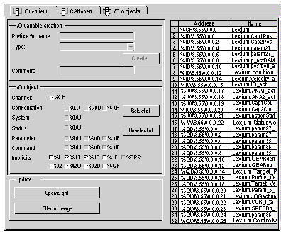
Open the \3.55\0.0†:†Lexium05 window by clicking on the Lexium module icon in the CANopen window. Click on the Lexium05 and then on the I/O object tab.
|
|
2
|
Click on the I/O object prefix address %CH then on the Update grid button, the channel address appears in the I/O object grid.
|
|
3
|
Click on the line %CH\3.55\0.0 and then, in the I/O object creation window, enter a channel name in the prefix for name zone, Lexium for example.
|
|
4
|
Now click on different Implicit I/O object prefix adresses then on update grid button to see the names and addresses of the homicide I/O objects.
 |