|
Starting the Application
|
|
|
(Original Document)
|
|
Step
|
Action
|
|---|---|
|
1
|
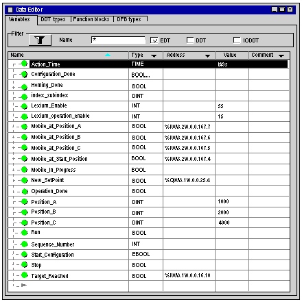
In the Project browser and in Variables & FB instances, double-click on Elementary variables.
|
|
2
|
In the Address column, enter the address associated with the variable in the form \Bus.Node\Rack.Module.Channel.Data.
 |
|
3
|
Repeat the same procedure for all located variables.
|
|
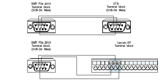
Pin number
|
Symbol
|
Description
|
|---|---|---|
|
1
|
-
|
Reserved
|
|
2
|
CAN_L
|
CAN_L bus line (Low)
|
|
3
|
CAN_GND
|
CAN ground
|
|
4
|
-
|
Reserved
|
|
5
|
Reserved
|
Optional CAN protection
|
|
6
|
(GND)
|
Optional ground
|
|
7
|
CAN_H
|
CAN_H bus line (High)
|
|
8
|
-
|
Reserved
|
|
9
|
Reserved
|
CAN external positive supply (optionnal)
|
|
Pin number
|
Symbol
|
Description
|
|---|---|---|
|
1
|
-
|
Reserved
|
|
2
|
CAN_L
|
CAN_L bus line (Low)
|
|
3
|
CAN_GND
|
CAN ground
|
|
4
|
-
|
Reserved
|
|
5
|
(CAN_SHLD)
|
Optional CAN protection
|
|
6
|
(GND)
|
Optional ground
|
|
7
|
CAN_H
|
CAN_H bus line (High)
|
|
8
|
-
|
Reserved
|
|
9
|
-
|
Reserved
|
|
Pin number
|
Symbol
|
Description
|
|---|---|---|
|
21
|
CAN_GND
|
CAN ground
|
|
22
|
CAN_L
|
CAN_L bus line (Low)
|
|
23
|
CAN_H
|
CAN_H bus line (High)
|
|
Step
|
Action
|
|---|---|
|
1
|
Shut down the STB.
|
|
2
|
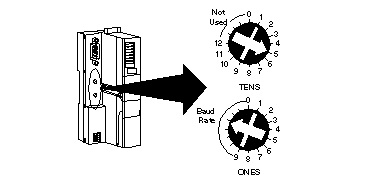
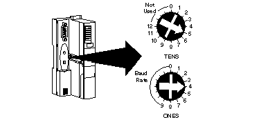
Using the rotary switches (located on the front of the CANopen NIM), configure the baud rate. The rotary switches are positionned as followed (5 = 500 kbits/s):
 |
|
3
|
Start up then shut down the STB.
|
|
4
|
Using the rotary switches, configure the address of the STB. For example, is the node number of the equiment is 54, the rotary switches are positionned as followed:
 |
|
5
|
Start up the STB and press the reset button located on the STB NCO module during for 5 seconds.
|
|
6
|
The STB is configured automatically.
|
|
Step
|
Action
|
|---|---|
|
1
|
Start up the Lexium 05. RDY is displayed on ther interface.
|
|
2
|
Press Enter
|
|
3
|
Press the down arrow key until COM- is displayed. Then press Enter.
|
|
4
|
Press the down arrow key until CoAD (CANopen Address) is displayed. Then press Enter.
|
|
5
|
Using the arrow keys, configure the node number. Then press Esc.
|
|
6
|
Press the down arrow key until CoBD (CANopen Baud Rate) is displayed. Then press Enter.
|
|
7
|
Using the arrow keys, configure the baud rate (500). Then press Esc.
|
|
8
|
Press the Esc until RDY displayed.
|