|
Configuration of an Altivar Variable Speed Controller
|
|
|
(Original Document)
|
|
Step
|
Action
|
|---|---|
|
1
|
Launch the Sycon software and create a new CANopen project.
Result: you should obtain bus architecture of this type:
 |
|
2
|
Select the command Insert → Node.
Result: a cursor appears:
|
|
3
|
Place the cursor on the bus outside of the text frame that defines the master and click once.
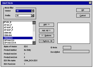
Result: The following screen appears:
 |
|
4
|
Select the Altivar EDS file that you would like to incorporate into the bus and click on Add.
Note: Four Altivars are available:
|
|
5
|
Confirm your selection with OK.
Result: the bus architecture shows a new node made up of a drive. You must now configure the PDOs of this drive.
|
|
6
|
Double click on the drive node to display the PDO window.
Result: a screen resembling the Advantys STD screen appears, allowing you to configure the two PDOs for the drive:
|
|
7
|
Double click on each PDO and confirm the default transmission parameters.
|
|
8
|
Check that the node speeds and its address correspond to those that you set in the Altivar.
Note: If Altivar is the last element of the bus, do not forget to activate the bus end termination by setting the switch located on the Altivar CANopen communication card.
|
|
9
|
Click OK to confirm the node configuration.
|
|
10
|
Save the .CO file.
|
|
11
|
Open your Control Expert project that contains the master of the CANopen bus (TSX CPP 110 card), declare the card, import the saved .CO file, generate the project and transfer it to the PLC as in the Advantys STD example.
Result: the CANopen bus and your Altivar are operational.
|