|
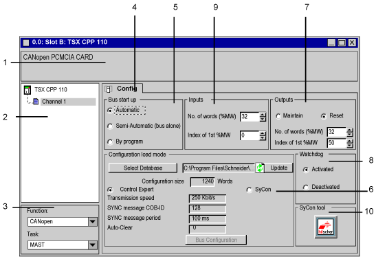
Configuration of the PCMCIA TSX CPP 110 Card
|
|
|
(Original Document)
|

|
Zone
|
Number
|
Function
|
|---|---|---|
|
Module
|
1
|
This zone comprises the abbreviated title of the PCMCIA card that you declared, which must be a CANopen card.
|
|
Channel
|
2
|
This zone allows you to select the communication channel to be configured.
Click on the channel to obtain the configuration tab.
|
|
General parameters
|
3
|
In this zone, select the task associated with the I/Os located on the CANopen bus. The selected task will determine the acquisition rate of the inputs and update of the outputs of the CANopen bus slaves.
In our case, we will select the master (MAST) task.
|
|
Tab
|
4
|
The tab in the foreground indicates the type of screen displayed. In our case it is the configuration screen. If you are in online mode, you will be able to access other tabs.
In this case, check that you have clicked on the Config. tab to obtain the screen shown in the illustration.
|
|
Config
|
5
|
This zone is used to select how the bus is to behave at start-up.
Select Automatic.
|
|
6
|
This zone is used to configure the bus.
Click on the Control Expert button in order to access the configuration using Control Expert.
Select the Demo_cfg.co file that you created with the Sycon software.
Result: the bus parameters are displayed when a .CO file is selected.
Note: If you modify the .CO file using Sycon, click the Update button in order to reload it into the configuration.
Note: If you wish to display the list of slaves on the bus, click the Bus configuration button.
|
|
|
7
|
This zone is used to configure the fallback mode for bus device outputs as well as the address (PLC internal memory) where the outputs from CANopen devices will periodically be read.
In our example, we select Reset and a number of 32 words starting at the address 50 (%MW50 to %MW81).
Later on we will see that these addresses correspond to topological objects (that depend on the slave in which they are located).
|
|
|
8
|
This zone is used to activate or deactivate the CANopen bus watchdog. The watchdog is activated by default. It is triggered when the PCMCIA card can no longer manage the bus correctly. When it is triggered, it makes all the slaves’ outputs change to zero.
In our example, we will leave it activated.
|
|
|
9
|
This zone is used to configure the address (PLC internal memory) to which inputs from the CANopen devices will periodically be copied.
In our example, we will retain the default values of 32 and 0 to indicate that the inputs will be stored in the words %MW0 to %MW31.
Topological addressing is also available as for the outputs.
|
|
|
10
|
This button is used to start the Sycon software, if it is installed on the PC.
|
 WARNING WARNING |
|
UNEXPECTED APPLICATION BEHAVIOR
Before deactivating the watchdog, ensure that, if the PCMCIA card does not manage the CANOpen bus, then the devices behavior remain acceptable.
Failure to follow these instructions can result in death, serious injury, or equipment damage.
|