|
Configuring EtherNet/IP Connections
|
|
|
(Original Document)
|
|
Step
|
Action
|
|
|---|---|---|
|
1
|
Open the DTM for the communications module—in this example NOC01—by selecting it in the Device Editor, then do one of the following:
The communication module DTM opens in the Device Editor.
|
|
|
2
|
In the navigation pane (on the left side of the Device Editor) select the node representing the connection from the communication module to the remote device, in this case:
Device List → NIC2212_01 → Read Input / Write Output Data
|
|
|
3
|
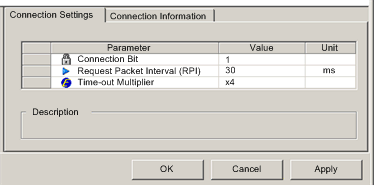
Click on the Connection Settings tab to open the following page:
 NOTE: You can view the Time-out Multiplier parameter, when Control Expert is operating in Advanced Mode. |
|
|
4
|
In the Connection Settings page, edit the following settings:
|
|
|
Connection Bit
|
(Read-only) The offset for both the health bit and the control bit for this connection. Offset values are auto-generated by the Control Expert Ethernet Configuration Tool, beginning at 0, and are prioritized according to the connection type, as follows:
1
Modbus TCP connections
2
local slave connections
3
EtherNet/IP connections
NOTE: The initial value of this EtherNet/IP connection is 1, because only a single local slave has previously been enabled. When a single Modbus TCP connection is created, the value of this connection bit offset changes to 2. |
|
|
Request Packet Interval (RPI)
|
The refresh period for this connection, from 2 to 65535 ms. Default = 12 ms. Type in 30 ms.
NOTE: This parameter can be set in the DTM for the communication module or the remote device. |
|
|
Time-out Multiplier
|
This setting, multiplied against the RPI, produces a value that triggers an inactivity timeout. Setting selections include: x4, x8, x16, x32, x64, x128, x256 and x512.
Accept the default of x4.
|
|
|
NOTE: The Connection Information page is read-only when the communication module is selected. This information needs to be set in the DTM for the remote device. |
||
|
5
|
Click OK to save your settings.
|
|
|
Step
|
Action
|
|
|---|---|---|
|
1
|
Open the DTM for the remote device—in this example NIC2212_01—by selecting it in the Device Editor, then do one of the following:
The remote device DTM opens in the Device Editor.
|
|
|
2
|
In the navigation pane (on the left side of the Device Editor), confirm that the remote device connection is of the type Read Input / Write Output Data. To view the connection type, select NIC2212_01 in the left pane of the Device Editor. If the connection type is not of the type Read Input / Write Output Data, delete the existing connection and add a new one, as follows:
|
|
|
a
|
With the connection selected in the left pane, click the Remove Connection button. The existing connection is removed.
|
|
|
b
|
Click the Add Connection button. The Select the connection to add dialog opens.
|
|
|
c
|
Use the scroll buttons on the drop down list to display and select the Read Input / Write Output Data connection type.
|
|
|
d
|
Click OK to close the Select the connection to add dialog. The new connection node appears.
|
|
|
e
|
Click Apply to save the new connection, leaving the Device Editor open for additional edits.
|
|
|
3
|
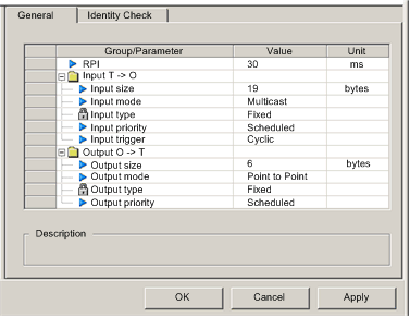
With the Read Input / Write Output Data node selected, click on the General tab:
 |
|
|
4
|
In the General page, edit the following settings:
|
|
|
RPI
|
The refresh period for this connection. Accept the value of 30 ms. (This parameter can be set in the DTM for the communication module or the remote device.)
|
|
|
Input size
|
The number of bytes reserved for input data, from 0 to 505. Type in 19.
NOTE: Control Expert reserves input data in increments of 2 bytes (1 word). In this example, typing in the value of 19 bytes reserves 20 bytes of input memory. |
|
|
Input mode
|
The transmission type:
Accept the default selection of Multicast.
|
|
|
Input type
|
Ethernet packet type—fixed or variable length—to be transmitted. Only Fixed length packets are supported.
|
|
|
Input priority
|
The transmission priority. The value depends upon the device DTM. Values can include:
NOTE: For remote modules that support more than one priority value, you can use this setting to specify the order in which the Ethernet communication module will handle packets. For more information, refer to the topic describing QoS Packet Prioritization. For the purpose of this example, accept the default selection of Scheduled.
|
|
|
Input trigger
|
The transmission trigger. Values can include:
For input I/O data, select Cyclic.
|
|
|
Output size
|
The number of bytes reserved for output data, from to 509. Type in 6.
NOTE: Control Expert reserves output data in increments of 2 bytes (1 word). |
|
|
Output mode
|
Accept the default selection of Point to Point.
|
|
|
Output type
|
(Read-only). Only Fixed length packets are supported.
|
|
|
Output priority
|
Accept the default selection of Scheduled.
|
|
|
5
|
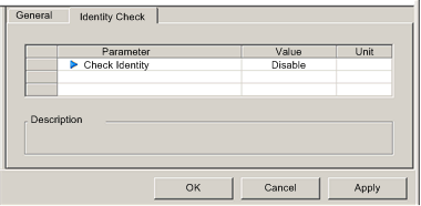
Click on the Identity Check tab to open the following page:
 |
|
|
6
|
In the Identity Check page, set rules for comparing the identity of the remote device, as defined by its DTM or EDS file, against the identity of the actual remote device located on the network. Complete the following settings:
|
|
|
Check Identity
|
Define the rule Control Expert will use in comparing the configured versus the actual remote device. Settings include:
For this example, select Disable.
|
|
|
If Check identity is set to Custom, complete the following 6 fields:
|
||
|
Compatibility Mode
|
|
|
|
Minor Version
|
For each of the parameters to the left, select one of the following settings:
|
|
|
Major Version
|
||
|
Product Code
|
||
|
Product Type
|
||
|
Product Vendor
|
||
|
7
|
Click OK to save your settings.
|
|