|
Connecting to the Advantys STB Island
|
|
|
(Original Document)
|
|
Step
|
Action
|
|---|---|
|
1
|
Startup the Advantys configuration software on your PC. A dialog opens displaying available project types.
|
|
2
|
Select STB.
|
|
3
|
Select File → New Workspace. The New Workspace window opens (below).
|
|
4
|
For this example, type in the following field values:
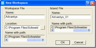 |
|
5
|
Click OK. The Advantys configuration software displays an empty DIN rail in the center of the screen.
|
|
6
|
Select Online → Connection Settings. The Connection Settings window opens (below).
|
|
7
|
In the Connection Settings window, accept the Modbus Node ID default setting of 1, select TCP/IP, and click the Settings... button:
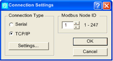 The TCP/IP Parameters dialog opens (below).
|
|
8
|
In the Remote IP Address field, type in the IP address for the STB NIC 2212, in this example: 192.168.1.6.
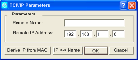 |
|
9
|
Click OK to close the TCP/IP Parameters dialog, and click OK again to close the Connection Settings dialog.
|
|
10
|
Select Online → Connect. The Data Transfer dialog opens (below):
 |
|
11
|
Select Upload in the Data Transfer dialog. The island workspace is populated with island data and shows the STB NIC 2212 and the island modules (below):
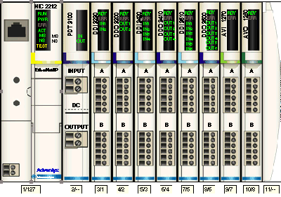 Note: A box appears beneath each module containing one or two integers—for example
 . These integers serve the following purpose: . These integers serve the following purpose:
|
|
12
|
Select Island → I/O Image Overview. The I/O Image window opens to the Fieldbus Image page:
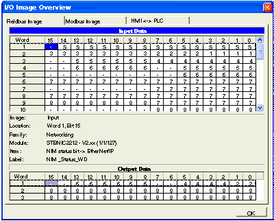 Each table cell contains one of the following alpha-numeric indicators:
Notes:
Select a cell in either the Input Data or Output Data tables to display—in the middle of the page—a description of the cell data and its source module.
Convert the size of the Input Data table and the Output Data table from words to bytes (i.e. divide by 2), then use that data as the values for the Input Size (19) and Output Size (6) parameters when configuring the remote device’s connection properties.
|