

Overview
You can open the either way:
By selecting more than one PAC or device and clicking in the context menu of either one. This selects the corresponding objects when the view opens.
By using the menu in the toolbar.
The view lists the PACs and devices that exist in your system project and to which you can deploy an executable or a DTM configuration respectively from the Topology Manager. It shows the status of these objects and lets you deploy to several objects in sequence.
The view lets you also perform the following actions on one or more PACs:.
Send run and stop commands.
The view is refreshed when you or other users update the topology of the system project.
Closing the
When you close the view, the action that is in progress completes but actions that are queued are canceled.
Description
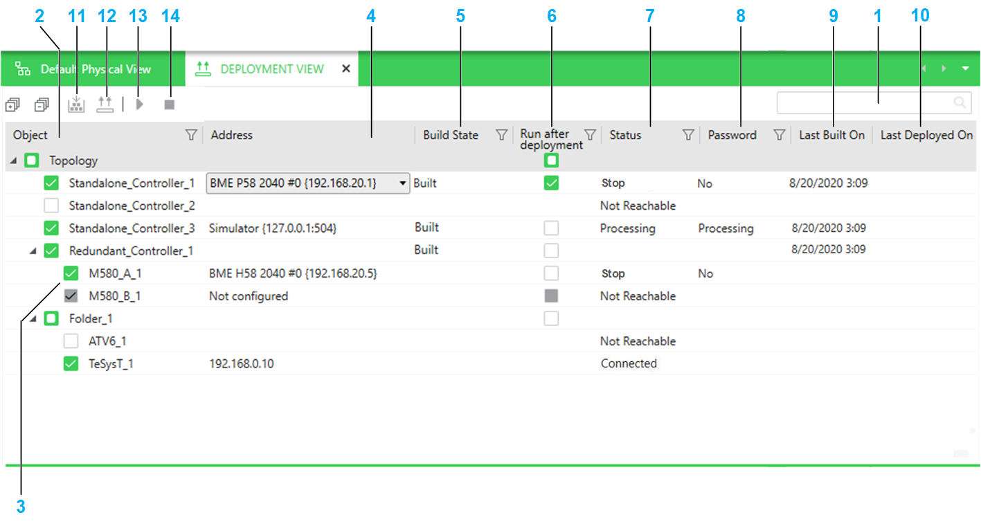
The following figure shows an example of the .
Item |
Description |
|---|---|
1 |
Search field. Enter one or more terms separated by a space and the pane displays objects whose name contains any of these terms. Objects are displayed with their parent structure. |
2 |
The column shows the name of the following objects that exist in the system project:
For redundant PACs, local racks A and B are shown separately. The view reproduces the entire folder structure of the node. When you select an object by selecting its check box, the software attempts to connect to the object and a status is indicated in the column. The simulator is automatically started if is set to . NOTE: Selecting or clearing the check box of an
object after clicking the or button adds it to or removes it from either queue respectively.
|
3 |
For redundant PACs, local racks A and B are shown separately. The executable is deployed to the respective controller only if its rack is selected. When the attribute is set to or , the check box of the corresponding rack is disabled and you cannot deploy to it. |
4 |
The column indicates the IP address that is used to connect to the object and deploy to it. You can choose from the following once the object is selected:
The address remains visible when the check box is cleared. Selecting an IP address attempts to connect to the object by using this address. |
5 |
Indicates the build state of the control project of the PAC. In addition, the following states can be indicated:
For devices, the column is always blank. |
6 |
Selecting the check box sends a run command after deployment completes successfully. The check box appears only for a PAC and when it is selected. |
7 |
Status of the object. The following statuses can be indicated:
After having deployed to all selected objects, successfully or not, the software refreshes the status of all these objects. |
8 |
The lets you store a password that it uses when a password is required to deploy to a PAC. You can set and change the password by using the context menu command. This has no impact on the application password that is set in the control project. The following application password-related conditions can be indicated:
For devices, the status is always . |
9 |
A value is shown only when is either or and the PAC is selected. For devices, the column is always blank. |
10 |
A value (date and time) is shown only if the configuration has been successfully deployed and the object is selected. Otherwise, blank. For a PAC, the deployment may have been performed either from the Topology Manager or Control Expert Editor. |
11 |
Builds the control projects of the PACs that are selected, in sequence, after you confirm the command. For each control project, the build operation starts only if the prerequisites are fulfilled. |
12 |
Starts the deployment to the objects that are selected, in sequence, after you confirm the command. If a CPU is in run state, it is stopped. The button is enabled only if at least one object is selected and the software was able to connect to it. |
13 |
Sends a run command to the CPU of each PAC that is selected and whose status is shown as in the view. You need to confirm the command. NOTE: For a redundant PAC, the command is sent to the CPU modules of controllers A and
B based on their respective selection. To view the controller states,
edit the control project.
|
14 |
Sends a stop command to the CPU of each PAC that is selected and whose status is shown as in the view. You need to confirm the command. NOTE: For a redundant PAC, the command is sent to the CPU modules of controllers A and
B based on their respective selection. To view the controller states,
edit the control project.
|