Character Mode Communication
 
Character Mode Communication Configuration Screen
To access the Character mode communication configuration screen, open the SerialPort sub-directory in the project browser ..., and select the Character mode link function.
The following figure shows the default configuration screen for Character mode communication:
These zones are used to configure channel parameters. In the online mode, these zones are accessible. In the offline mode, these zones are accessible but some parameters may not be accessible and are grayed out.
The following table shows the different zones of the Character mode communication configuration screen:
Key
Element
Comment
1
Message end detection parameters
This parameters are accessible via two zones:
  • Stop on reception
  • Stop on silence
2
Transmission parameters
This parameters are accessible via four zones:
  • Transmission speed
  • Data
  • Stop bits
  • Parity
3
Signal and physical line parameters
This parameters are accessible via three zones:
  • Physical line
  • Signals
  • RTS/CTS delay
Accessible Functions in Character Mode
The following table shows the different functions configurable according to the type of serial link used:
Function
RS485 Link
RS232 Link
Transmission speed
X
X
Data
  • 7 bits
  • 8 bits
  • 7 bits
  • 8 bits
Stop
  • 1 bit
  • 2 bits
  • 1 bit
  • 2 bits
Parity
  • Odd
  • Even
  • None
  • Odd
  • Even
  • None
Stop on reception
X
X
Stop on silence
X
X
RX/TX Signals
X
X
RTS/CTS Signals
-
X
RTS/CTS delay
-
X
X: Accessible function
-: Inaccessible function
The following table shows the default values for Character mode communication parameters:
Configuration parameter
Value
Physical Line
RS232
Transmission speed
9,600 bits/s
Parity
Odd
Data Bits
8 bits
Stop bits
1 bit
Message End Detection Parameters in Character Mode
After configuring the communication channel, enter the message end detection parameters.
These parameters are accessible via two zones:
Selecting Stop on silence means that Stop on reception is deselected and vice versa.
The following table describes the zones:
Zone
Screen
Description
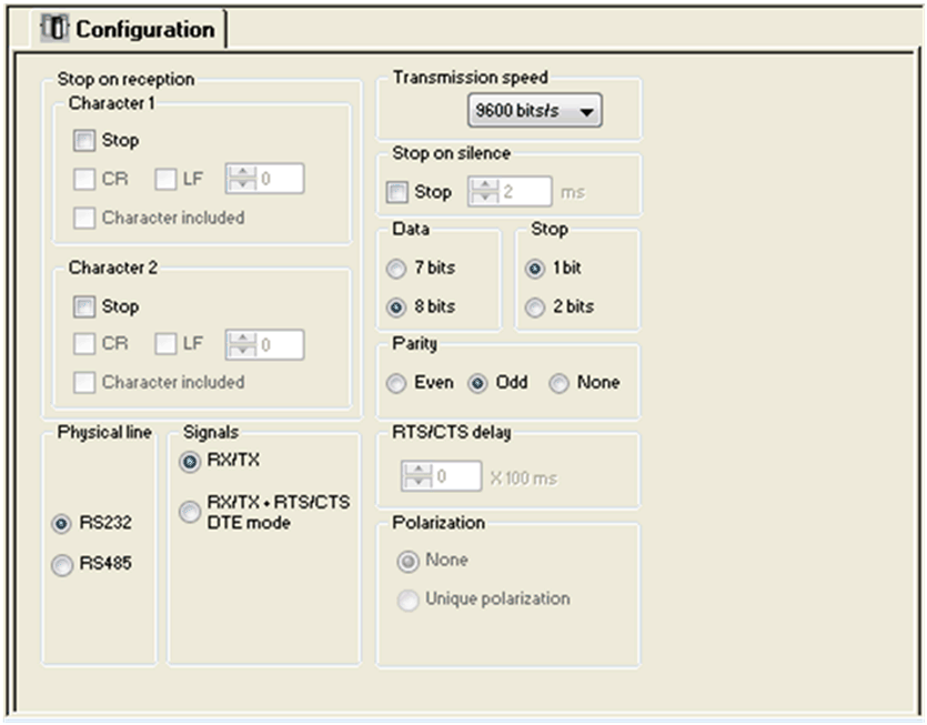
The Stop on reception zone
A reception request can be terminated once a specific character is received.
Select the Stop option to configure the Stop on reception feature which can be activated by a specific end-of-message character:
  • CR: enables you to detect the end of the message by a carriage return.
  • LF: enables you to detect the end of the message by a line feed.
  • Data entry field: enables you to identify an end-of-message character other than the CR or LF characters, using a decimal value:
    • Between 0 and 255 if the data is coded over 8 bits
    • Between 0 and 127 if the data is coded over 7 bits
  • Character included: enables you to include the end-of-message character in the reception table of the PLC application.
It is possible to configure two end-of-reception characters. For example, the end-of-reception of a message can be detected by an LF or CR character.
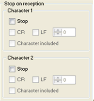
The Stop on silence zone
This zone enables you to detect the end of a message on reception by the absence of message end characters over a given time. Stop on silence is validated by checking the Stop check box. The duration of the silence (expressed in milliseconds) is set using the data entry field.
NOTE: The available values range from 1…10,000 ms depending on the transmission speed selected.
Transmission Parameters in Character Mode
The transmission parameters in Character mode is same as Modbus Serial communication .
Signal and Physical Line Parameters in Character Mode
After configuring the communication channel, enter the signal and physical line parameters.
These parameters are accessible via 3 zones:
The following table describes the zones:
Zone
Screen
Description
The Physical line zone
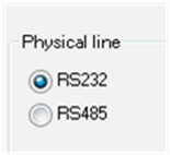
In this zone, you can select the line for the channel 0 of the CPU between:
  • The RS232 line
  • The RS485 line
The Signals zone
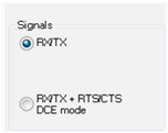
In this zone, you can select the signals supported by the RS232 physical line:
  • RX/TX
  • RX/TX + RTS/CTS Full Duplex (DTE mode)
If the RS485 is configured, the entire zone is grayed out and the default value is RX/TX.
The RTS/CTS delay zone
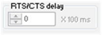
The RTS/CTS delay zone is available only when both RS232 and RX/TX+RTS/CTS check boxes are selected.
An RTS/CTS flow control algorithm is selected:
before a character string is transmitted, the system waits for the CTS (Clear To Send) signal to be activated. This zone enables you to enter the maximum waiting time between the two signals. When this value is timed out, the request is not transmitted on the bus. The Configurable values range from 0...10 s.
NOTE: The default value is 0 ms.
NOTE: A value of 0 s indicates that the delay between the two signals is not managed.
Character Mode Communication Programming
The three specific communication functions are defined for sending and receiving data via communication channel in Character mode:
Since the Modicon MC80 PLC serial port is full duplex with RS232 link, a PRINT_CHAR function can be sent when an INPUT_CHAR function is sent and is in pending state.
NOTE: For INPUT_CHAR function, a configured time-out is necessary to acknowledge the activity bit of the function, if the channel is configured without Stop on silence. For PRINT_CHAR function, it is advisable but not necessary to configure a time-out.