The serial links of the CPU support two communication protocols:
-
Modbus Serial
-
Character Mode
Modbus is a standard protocol with the following properties:
-
Establishes client/server communication between different modules within a bus or serial link. The client is identified by the master and the slave modules represent the servers.
-
Composes of requests and responses data exchange modes and offers services via function codes.
-
Establishes a means of exchanging frames from Modbus applications in two types of code; RTU mode and ASCII mode.
Character mode is a point-to-point mode of data exchange between two entities. It does not establish hierarchically structured serial link communications or offer services via function codes, unlike Modbus protocol. Character Mode is asynchronous.
Each item of textual information is sent or received character by character at irregular time intervals. The time taken by the exchanges can be determined from the following properties:
Communicating via Serial link enables data exchange between all devices connected to the bus. The Modbus Serial is a protocol that creates a hierarchical structure (one master and several slaves).
The master manages all exchanges in two ways:
NOTE: Be careful that two masters (on the same bus) do not send requests simultaneously otherwise the requests are lost and each report will have a bad result which could be 16#0100 (request could not be processed) or 16#ODFF (slave is not present).
The below table describes the procedure for accessing the serial link:
|
Step
|
Action
|
|
1
|
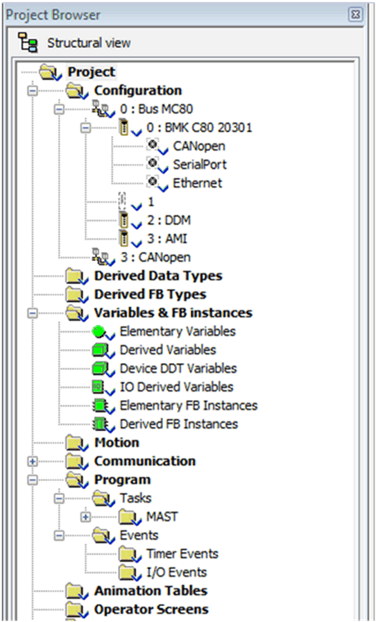
In the Project Browser, open the following directory: Station\Configuration\0: Bus MC80\0: processor reference\SerialPort.
The following screen appears:
|
|
2
|
Double-click the SerialPort sub-directory. The configuration screen appears.
|
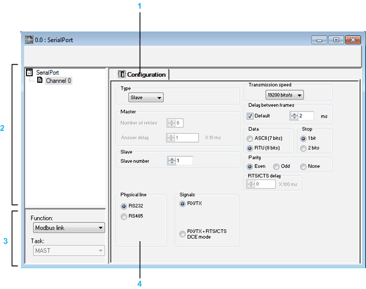
The following is the configuration screen:
The following table describes the different elements of the configuration screen:
|
Address
|
Element
|
Function
|
|
1
|
Tabs
|
The tab in foreground indicates the current mode. The mode can be selected using the corresponding tab. The available modes are:
|
|
2
|
Channel zone
|
Enables you to:
-
Select between the serial port and channel 0 by clicking one or the other.
-
Display the following tabs by clicking the SerialPort:
-
Display the following tabs by clicking the Channel 0:
-
Display the channel name and symbol defined by the user using the variables editor.
|
|
3
|
General parameters zone
|
This enables you to choose the general parameters associated with the channel:
-
Function:The available functions are Modbus and Character Mode. The default configuration is with the Modbus function.
-
Task: Defines the master task in which the implicit exchange objects of the channel will be exchanged. This zone is grayed out and therefore not configurable.
|
|
4
|
Configuration zone
|
In configuration mode, this zone is used to configure the channel parameters.
|

