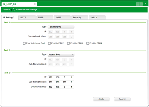
|
Configuring IP Addresses
|
|
|
(Original Document)
|

|
Type
|
Description
|
Available
|
||
|---|---|---|---|---|
|
Port 1 (ETH 1)
|
Port 2 (ETH 2)
|
Ports 3/4 (ETH 3/4)
|
||
|
Access Port
|
Diagnostic information is available via explicit messaging (Modbus) or via SNMP.
NOTE: A port set to Access Port type uses the IP address of the network that is set for Ports 3/4. |
√
|
√
|
–
|
|
Extended Network
|
You can extend the device network by adding another network to this port.
|
√
|
√
|
–
|
|
Port Mirroring
|
You can connect to this port via a PC and use packet sniffing software to analyze the traffic traveling through one or more of the other module ports.
|
√
|
–
|
–
|
|
Dedicated Network Ports
|
Ports 3 and 4 (ETH 3 and ETH 4) share a single IP address and are dedicated connections.
NOTE: Ports 3 and 4 (ETH 3 and ETH 4) support RSTP. |
–
|
–
|
√
|
|
√ The port type is available for this port.
– The port type is not available for this port.
|
||||
|
Setting
|
Description
|
|---|---|
|
Type
|
Select the role to assign to the port. Selections include:
|
|
IP
|
A 32-bit IP address assigned to the port, including both network and host components.
|
|
Sub-Network Mask
|
A 32-bit value used to mask the network portion of the IP address and reveal the host address.
|
|
Default Gateway
|
For Port 3/4, the IP address of the router that is the access point to a remote network.
NOTE: 0.0.0.0 is a valid setting. |
|
Step
|
Action
|
|
|---|---|---|
|
1
|
In the Port 1 area, select Port Mirroring as the port Type.
The check boxes at the bottom of the Port 1 area are enabled.
|
|
|
2
|
Select the ports whose traffic is mirrored and sent to Port 1:
|
|
|
Enable Internal Port
|
Select this to send a copy of traffic passing through the internal port (between the module internal router and the module CPU) to Port 1.
|
|
|
Enable ETH2
|
Select this to send a copy of traffic passing through Port 2 (ETH 2) to Port 1.
|
|
|
Enable ETH3
|
Select this to send a copy of traffic passing through Port 3 (ETH 3) to Port 1.
|
|
|
Enable ETH4
|
Select this to send a copy of traffic passing through Port 4 (ETH 4) to Port 1.
|
|
|
3
|
Click Apply to confirm your edits.
|
|
|
4
|
Click Save to save your edits.
|
|