Connecting the module TBX AES 400
(Original Document)
Circuit diagram
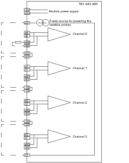
The following illustration shows the circuit diagram for the module TBX AES 400.
NOTE: the terminals + R• and - R• are a repetition of terminals + I• and - I• , and enable the shunt to be connected for the ranges 0..20 mA and 4..20 mA.
The terminals 0/1,1/2, 2/3 enable the daisy chaining of power supplies to resistive probes to be carried out. It is not essential to use them, however the current loop must be closed on -Is.
Terminal block wiring
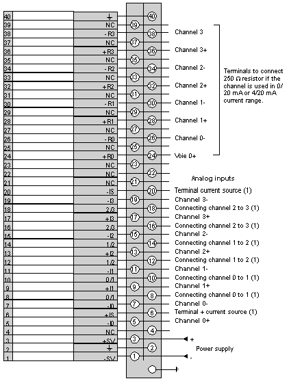
The following diagram illustrates the wiring of the terminal..
1 
Inputs to be used for the wiring of temperature probes.