Predefined Configuration File Name
C4_RIOMainRingFx_DIOSubRingTx_DIOCloudsVx.xx.cfg, where
Vx.xx references the version number of the file.
Use of this Predefined Configuration
In some applications, you may need to install distributed I/O devices a long distance (up to 15 km) from other devices on a Quantum EIO network. In other cases, the operating environment may require less susceptibility to electromagnetic interference (EMI) than a copper wire connection can provide. You can meet these needs by using single-mode or multi-mode fiber optic cable on the main ring of your network.
The relationship between the main ring and a distributed I/O sub-ring is essentially the same as with
only copper connections, with 2 key differences:
Devices Supported by this Predefined Configuration
The predefined configuration described here can be used with a DRS that supports either single-mode or multi-mode fiber cable:
Both switches have 6 copper connections. Fiber cable can be used only on the main ring, not on the sub-rings.
With single-mode fiber cable, you can achieve distances on the main ring up to 15 km. With multi-mode fiber cable, you can achieve distances up to 2 km.
Predefined Port Connections
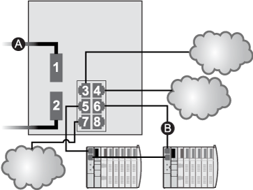
For this configuration, use the 2 fiber ports (labeled ports 1 and 2) for the main ring (A) connections. Use the 2 middle copper ports (labeled ports 5 and 6) to connect a distributed I/O sub-ring (B) to the main ring.
Ports 3, 4, and 7 on the DRS are available for additional optional connections, and can be used to connect distributed I/O clouds to the Quantum EIO system. Port 8 is reserved for
port mirroring, i.e., for monitoring the status of the ports you previously selected in the switch’s port mirror web page.
NOTE: The default configuration of port 8 has port mirroring disabled.
A
main ring (with 2 fiber connections)
B
distributed I/O sub-ring (with 2 copper connections to some STB distributed I/O islands)
|
Port
|
Type
|
Description
|
|
1
|
FX
|
fiber main ring connections
|
|
2
|
FX
|
|
3
|
100Base-TX
|
a distributed I/O cloud connection
|
|
4
|
100Base-TX
|
a distributed I/O cloud connection
|
|
5
|
100Base-TX
|
copper distributed I/O sub-ring connections
|
|
6
|
100Base-TX
|
|
7
|
100Base-TX
|
a distributed I/O cloud connection
|
|
8
|
100Base-TX
|
port mirroring connection
|
NOTE: When you download this DRS predefined configuration file to a switch, the file provides a set of operating parameters that enable the switch to operate with high efficiency in the specified architecture.
Do not adjust the configuration parameters or alter the port usage from what is shown above. Changing the configuration parameters or the port assignments can compromise the effectiveness and accuracy of the switch and the performance of the remote I/O network.
You can enable/disable port mirroring and change the selection of the source ports that you want mirrored. Port mirroring is disabled by default. The destination port is set to port 8, and ports 1-7 are selected as source ports. Do not change the destination port. When using port mirroring, select the ports, for which you want to analyze the traffic, as the source ports. When you finish troubleshooting, disable port mirroring.
Supporting Fiber Links on the Main Ring
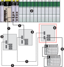
Remote I/O devices in the main ring often do not come equipped with fiber connectors. Therefore, some part of the main ring requires copper cable. A switch with an all-fiber main-ring predefined configuration (for example, DRS number 4 in the following diagrams) is usually implemented together with 2 other DRSs (3, below) each of which is configured to support 1 fiber connection and
1 copper connection to the main ring.
When you use a 140NOC78000 distributed I/O head module, interlink the module directly to the 140CRP31200 remote I/O head module in the local rack, as shown below:
1
the copper/fiber main ring
2
a 140CRP31200 remote I/O head module and a 140NOC78000 distributed I/O head module interlinked in the local rack
3
2 DRS with C5 or C6 predefined configuration files that are configured to use only 1 fiber port. They support a copper-to-fiber and fiber-to-copper transition.
4
a DRS with a C4 predefined configuration file that is configured to use both main ring fiber ports, and both distributed I/O sub-ring copper ports
5
a distributed I/O sub-ring with 2 STB islands 
