Predefined Configuration Files
Original instructions
Introduction
Schneider Electric provides several predefined configuration files for its 8-port TCSESM-E dual-ring switches (DRSs). You can use these predefined configuration files to quickly apply DRS configuration settings, instead of manually configuring switch properties.
Each configuration is specifically designed for a TCSESM-E DRS with either:
Apply a predefined configuration file only to a TCSESM-E DRS that is appropriate for that specific switch.
List of Switches
These 3 ConneXium extended managed switches are currently the only DRSs that are approved in a Quantum EIO system.
Part
ConneXium Switch
Ports
TCSESM083F23F1
8TX 1280
  • copper (8)
TCSESM063F2CU1
6TX/2FX-MM
  • multi-mode fiber (2)
  • copper (6)
TCSESM063F2CS1
6TX/2FX-SM
  • single-mode fiber (2)
  • copper (6)
NOTE: These 3 switches use firmware version 6.0 or greater.
NOTE: You can achieve up to 2 km with multi-mode fiber cables and up to 15 km with single-mode fiber cables in a Quantum EIO system.
Configuring an 8-Port TCSESM-E Dual-Ring Switch
When you download a predefined configuration file to a switch, the file provides a set of operating parameters that enable the switch to operate with high efficiency in the specified architecture.
Do not try to configure the switches yourself. The predefined configurations have been tested so that they meet the determinism and cable redundancy standards of the Quantum EIO system.
Except when enabling or disabling ports that are not connected to either a main ring or a sub-ring, do not adjust the configuration parameters or alter the port usage in the predefined configuration file. Changing the configuration parameters or the port assignments can compromise the effectiveness and accuracy of the switch, as well as the performance of the remote I/O network.
Port mirroring is disabled by default. The destination port is set to port 8, and ports 1-7 are selected as source ports. You can enable port mirroring and change the selection of the source ports that you want mirrored. Do not change the destination port. When using port mirroring, select the port(s), for which you want to analyze the traffic, as the source port(s).
WARNING
UNEXPECTED EQUIPMENT BEHAVIOR
Do not modify any parameter in the DRS predefined configuration you download to the switch, except enabling or disabling Ethernet ports.
You can enable/disable port mirroring and change the selection of the source ports that you want mirrored. Port mirroring is disabled by default. The destination port is set to port 8, and ports 1-7 are selected as source ports. Do not change the destination port. When using port mirroring, select the ports, for which you want to analyze the traffic, as the source ports.
Failure to follow these instructions can result in death, serious injury, or equipment damage.
WARNING
UNEXPECTED EQUIPMENT BEHAVIOR
Upgrading the firmware for a ConneXium extended managed switch removes all predefined configuration file settings. You need to re-download the predefined configuration file to the switch before placing the switch back in operation.
Failure to follow these instructions can result in death, serious injury, or equipment damage.
To determine which predefined configuration you need to download to each DRS in your network, refer to the following diagrams.
Dual-Ring Switch Labels
Labels are supplied in the ConneXium extended managed switch box. When you determine which predefined configuration you need to download to each DRS, write the respective configuration number on the label and affix to either side of the DRS.
DRS label with fiber/copper ports:
DRS label with copper ports only: TCSESM083F23F1 – 8TX 1280
Copper Main Ring Configurations
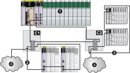
Some predefined configuration files let you use a TCSESM-E DRS — with 8 copper ports — to connect a remote I/O copper main ring to either a remote I/O sub-ring or a distributed I/O sub-ring:
C1
a DRS using the C1 predefined configuration file for a copper remote I/O main ring with a remote I/O sub-ring and distributed I/O clouds
C2
1
a local rack with a CPU, a 140CRP31200 remote I/O head module, and a 140NOC78000 distributed I/O head module
2
a remote I/O sub-ring
3
a distributed I/O sub-ring
4
distributed I/O clouds
Fiber Main Ring Configurations
NOTICE
UNINTENDED EQUIPMENT OPERATION
When installing modules with fiber optic transceivers, do the following to help prevent dust and pollution from disrupting light production into the fiber optic cable.
  • Keep caps on jumpers and transceivers when not in use.
  • Insert the optical cable into the transceivers carefully, respecting the longitudinal axis of the transceiver.
  • Do not use force when inserting the cable into the optical transceivers.
Failure to follow these instructions can result in equipment damage.
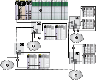
Some predefined configuration files let you use a TCSESM-E DRS — with 2 fiber ports and 6 copper ports — to connect a remote I/O copper main ring to either a remote I/O sub-ring or a distributed I/O sub-ring:
C3
C4
C5
C6
1
a local rack with a CPU, a 140CRP31200 remote I/O head module, and a 140NOC78000 distributed I/O head module
2
remote I/O sub-rings
3
distributed I/O sub-rings
4
distributed I/O clouds
Long-Haul Hot Standby Fiber Configuration
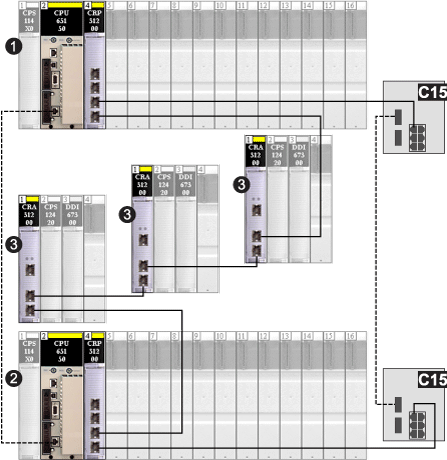
Some predefined configuration files let you use a TCSESM-E DRS — with 2 fiber and 6 copper ports — to extend a remote I/O copper main ring over a long haul distance using fiber optic cable.
NOTE: Do not connect any devices between the DRSs.
C15
2 DRSs using the C15 predefined configuration file for a fiber/copper connection for a long-haul link between Hot Standby systems
1
a local Hot Standby rack with a CPU and a 140CRP31200 remote I/O head module
2
a backup Hot Standby rack
3
3 remote I/O drops
Main Ring / Sub-Ring Redundant Connections
Use 2 DRSs — one installed with a master predefined configuration and the other installed with a corresponding slave predefined configuration — to provide a redundant connection between the main ring and the sub-ring. The master DRS passes data between the main ring and the sub-ring. If the master DRS becomes inoperable, the slave DRS takes control and passes data between the main ring and the sub-ring.
NOTE: Do not connect devices between the master and slave DRS. Connect at least 1 operating link between the master and slave DRS for the redundant connections to function properly.
NOTE:
DRS inner ports are the 2 ports on the switch that are connected to the main ring. When using 2 DRSs, connect the designated master inner ports to the designated slave inner ports.
  • For copper port master and slave DRS redundant configurations, the inner ports are port 2 for the main ring and port 6 for a sub-ring.
  • For copper/fiber port master and slave DRS redundant configurations, the inner ports are port 3 for the main ring and port 6 for a sub-ring.
If you are using a single DRS but plan to convert to redundant configurations in the future, make a note of these port configurations to minimize any schematic changes required because of the conversion.
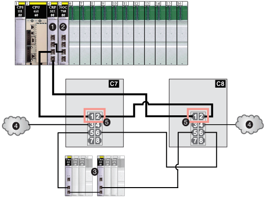
The example below shows 2 DRSs creating a redundant connection between the main ring and the remote I/O sub-ring.
C7
C8
1
a 140CRP31200 remote I/O head module
2
a 140NOC78000 distributed I/O head module
3
a remote I/O sub-ring
4
2 distributed I/O clouds
5
4 inner ports
Comparison of Master/Slave Configuration and Auto Configuration
In the DRS web pages, you can select one of the following configurations:
NOTE: In the event that both the master and slave DRSs lose communication and only the slave regains communication after a reboot, the slave — whether it has a master/slave or an auto configuration — is in a blocking state. The blocking state only changes to forwarding if the master DRS regains communication and its configuration is detected on at least one inner port.
Port Mirroring
In every predefined configuration, port 8 is reserved for port mirroring. Port mirroring lets you troubleshoot the transmissions sent over selected ports by copying the traffic that passes through these ports and sending the copied transmission to port 8, where you can examine the copied packets.
When using port mirroring, select the port(s), for which you want to analyze the traffic, as the source port(s) in the switch’s port mirror web page. Select port 8 as the destination port, and enable port mirroring.
NOTE: The default configuration of port 8 has port mirroring disabled.
NOTE: Port mirroring does not affect the normal forwarding behavior of the mirrored ports.
To troubleshoot the selected ports, attach a PC with packet sniffing software to port 8 to analyze the mirrored traffic. When you finish troubleshooting, disable port mirroring.