|


|
Original instructions
|
|
|
Original instructions
|
|
Step
|
Action
|
|---|---|
|
1
|
Write an MSTR block to the DRS managing the sub-ring of interest.
NOTE: Use the 140CRP31200 remote I/O head module to send MSTR commands to diagnose the status of sub-rings. For other operations (get remote statistics, read data, etc.), we recommend that you send an MSTR command from a 140 NOC 78• 00 head module. |
|
2
|
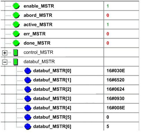
Read the states of ports 5 and 6 on the DRS. The possible port state values are:
1disabled 2blocking 3listening 4learning 5forwarding 6broken |
|
3
|
|
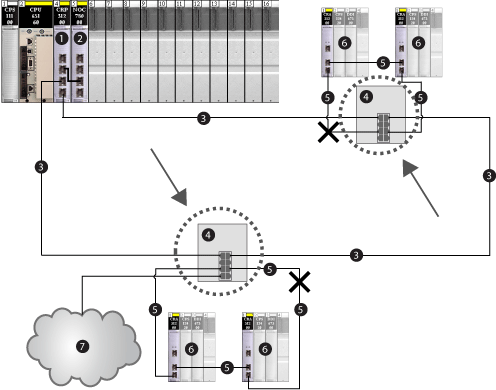
1140CRP31200 remote I/O head module on the local rack
2140NOC78000 distributed I/O head module interlinked with the head module
3main ring
4DRS connected to main ring and sub-ring
5remote I/O sub-ring
6remote I/O drops (including ••• CRA 312 00 adapter module)
7distributed I/O cloud connected to DRS (managed by the 140NOC78000 module)
|
class code
|
0x65 (hex)
|
|
instance
|
7 for port 6
|
|
attribute
|
9
|
|
service code
|
0x01 (hex) or 0x0E (hex)
|
|
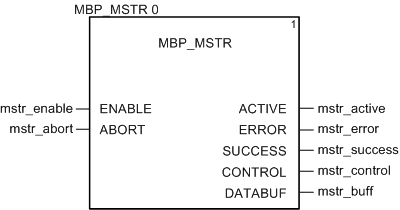
Input Pin
|
Variable
|
Data Type
|
|---|---|---|
|
ENABLE
|
mstr_enable
|
BOOL
|
|
ABORT
|
mstr_abort
|
BOOL
|
|
Output Pin
|
Variable
|
Data Type
|
|---|---|---|
|
ACTIVE
|
mstr_active
|
EBOOL
|
|
ERROR
|
mstr_error
|
EBOOL
|
|
SUCCESS
|
mstr_success
|
EBOOL
|
|
CONTROL
|
mstr_control
|
ARRAY
|
|
DATABUF
|
mstr_buff
|
ARRAY
|
|
Register
|
Description
|
Setting (hex)
|
|---|---|---|
|
CONTROL[0]
|
Operation
|
16#000E
|
|
CONTROL[1]
|
Detected error code (read-only, written by operation)
|
16#0000
|
|
CONTROL[2]
|
Data buffer length (reserving 100 words)
|
16#0064
|
|
CONTROL[3]
|
Response offset in words for the beginning of the explicit message response in the data buffer
|
16#000A
|
|
CONTROL[4]
|
High byte = slot number of the 140CRP31200 remote I/O head module
Low byte = Unit ID number
|
16#0400
|
|
CONTROL[5]1
|
IP address of the Ethernet communication module
|
16#C0A8
|
|
CONTROL[6]1
|
IP address of the Ethernet communication module
|
16#0106
|
|
CONTROL[7]
|
CIP request length (in bytes)
|
16#0008
|
|
CONTROL[8]
|
CIP response length (read-only, written by operation)
|
16#0000
|
|
1 In this example, The control parameter handles the IP address 192.168.1.6 in the following order: byte 4 = 192, byte 3 = 168, byte 2 = 1, and byte 1 = 6.
|
||