|
|
Original instructions
|
 CAUTION CAUTION |
|
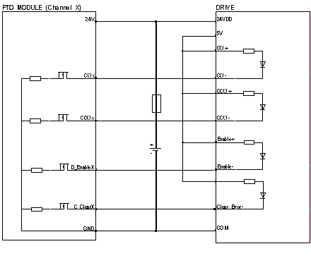
POTENTIAL MODULE DAMAGE - IMPROPER FUSE SELECTION
Use fast acting fuses to protect the electronic components of the module from overcurrent and reverse polarity of the input/output supplies. Improper fuse selection could result to damage to the module.
Failure to follow these instructions can result in injury or equipment damage.
|
|
NOTICE
|
|
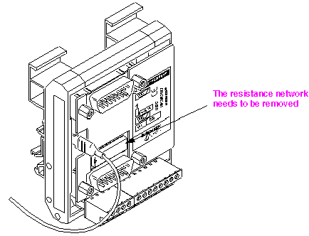
MATERIAL DESTRUCTION
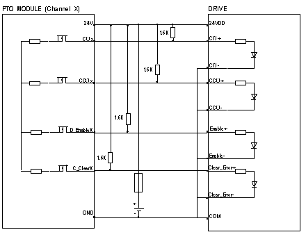
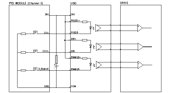
Remove the network resistance from the USIC.
Failure to follow these instructions can result in equipment damage.
|
 CAUTION CAUTION |
|
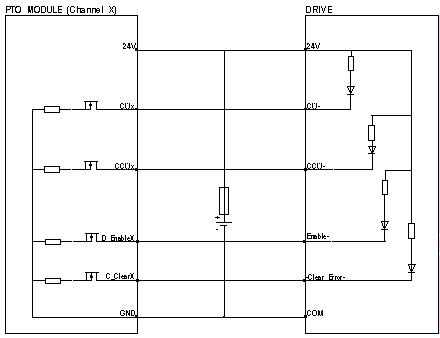
POTENTIAL MODULE DAMAGE - IMPROPER FUSE SELECTION
Use fast acting fuses to protect the electronic components of the module from overcurrent and reverse polarity of the input/output supplies. Improper fuse selection could result to damage to the module.
Failure to follow these instructions can result in injury or equipment damage.
|
 WARNING WARNING |
|
RANDOM COMMAND AND PERFORMANCE REDUCTION
Do not use a cable with a length above 0.5 m (1.64 ft).
Failure to follow these instructions can result in death, serious injury, or equipment damage.
|
 CAUTION CAUTION |
|
OUTPUT SHORT-CIRCUIT OR OVERLOAD
Respect mounting procedure and use the given wiring cable
Failure to follow these instructions can result in injury or equipment damage.
|