The PTO function provides a square wave output for a specified number of pulses and a specified cycle time.
The PTO function can be programmed to produce either one train of pulses or a pulse profile consisting of multiple trains of pulses. For example, a pulse profile can be used to control a stepper motor through a simple ramp up, run, and ramp down sequence or more complicated sequences. The control positioning is achieved according to an open loop mode, meaning without the need for feedback information on the real position. The position loop is integrated in the servo-drive.
Number of pulses is from -2,147,483,648 to 2,147,483,647 (32 bits depth)
Maximum frequency:
-
For CW / CCW and pulse/direction modes with a cable length up to 10 m (32.81ft), the maximum frequency is 200 kHz.
-
For A/B phases control mode the maximum frequency is 100 kHz.
Average frequency accuracy:
NOTE: There are some limitations in case of usage of USIC + Lexium 05 and a 24 V power supply
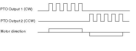
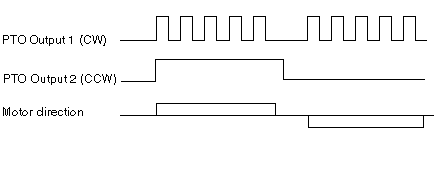
There are 3 types of pulse train output mode that can be configured.
Pulse+ /Pulse- (CW/CCW):
Pulse + direction:
A/B phases (Quadrature):
In order to select the axis movement direction in accordance with the motion command direction on the PTO module, the Control Expert Software has 3 pulse-train output configuration modes for the PTO module, each allowing reverse direction.


 WARNING