|
GetTabResultF: Trajectory Calculation Result (ACTION_TRF = 16901)
|
|


|
(Original Document)
|
|
GetTabResultF: Trajectory Calculation Result (ACTION_TRF = 16901)
|
|
|
(Original Document)
|
|
Parameter
|
Description
|
|---|---|
|
%CHr.m.c
|
Channel associated with module channel group consisting of the slave axes and master axis of the trajectory for which information is required.
Example: %CH3.21
|
|
Table_length
|
Number of words in the reception table: Table_length = 4 x number of points in trajectory.
|
|
Reception_table
|
First word in the table to which the values requested by parameter param_trf_3 have been assigned. This table contains two floating points for each point on the trajectory. These words contain the speeds (param_trf_3 = 1.0 or 2.0) or the characteristic positions for each segment type (param_trf_3 = 0.0). A more detailed description of the information received when you wish to obtain the position of the master appears below.
Example: %MW0:
|
|
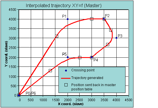
Point
|
X
|
Y
|
Type
|
Master position
|
Point on illustration
|
|---|---|---|---|---|---|
|
P0
|
0
|
0
|
Not known
|
0
|
Always 0
|
|
0
|
Always 0
|
||||
|
P1
|
2000
|
4000
|
10
|
3472,136
|
End of linear section between P0 and P1, start of circular link
|
|
5263,540
|
End of circular link at P1
|
||||
|
P2
|
3500
|
4000
|
0
|
5263,540
|
End of linear section between P1 and P2
|
|
5263,540
|
End of linear section between P1 and P2
|
||||
|
P3
|
4000
|
3000
|
10
|
6381,574
|
End of linear section between P2 and P3, start of circular link
|
|
7248,053
|
End of circular link at P3
|
||||
|
P4
|
3000
|
2000
|
0
|
8162,267
|
End of linear section between P3 and P4
|
|
8162,267
|
End of linear section between P3 and P4
|
||||
|
P5
|
2000
|
2000
|
1
|
8162,267
|
End of linear section between P4 and P5, start of third-degree link
|
|
10161,267
|
End of third-degree link at P5
|
||||
|
P6
|
0
|
0
|
Linear link
|
11990,695
|
End of linear section between P5 and P6 (total master length)
|
|
11990,695
|
End of linear section between P5 and P6 (total master length)
|