|
Linear Interpolation With 5º Polynomial Interpolation Connection: Type 2
|
|
|
(Original Document)
|

|
Parameter
|
Description
|
|---|---|
|
ParW0
|
Enter 2 to indicate that the type of interpolation to be used is linear interpolation with 5° polynomial interpolation connection.
|
|
ParW1 = NpLin
|
Indicate the number of points in the linear part of the segment in this parameter. This number of points (minimum 1) represents the number of intermediate points that the module has to calculate in order to define the trajectory on this linear part.
|
|
ParW2 = NpRacc
|
Indicate the number of points in the 5° interpolation part of the segment in this parameter. This number of points (minimum 1) represents the number of intermediate points that the module has to calculate in order to define the trajectory on this part. It should be enough to ensure precision of the trajectory, and a minimum value of 15 is recommended.
|
|
ParW3 = KF
|
5° interpolation shape coefficient. Between 50 and 200 this coefficient can be used to modify the shape of the connection zone. The default value is 100, and it is advisable to keep this default value if the desired movement allows, as it ensures that there will not be any motion "overshoot".
Note: The more the KF coefficient increases, the nearer the curve comes to the segment characteristic point, and the more it decreases, the further away the curve goes.
|
|
ParW4
|
For this type of segment, only tangent mode can be used. If a third tangent type axis is being used, select tangent mode (bit 8 of ParW4 at 1) to indicate that the motion of the third axis will follow the curve using tangent mode (positioning a tool for example so that it is always at right-angles to the curve and follows its tangent).
Note: Tangent mode (bit 8 at 1) will be available in a later version of the TjE/TSX CSY 85 combination, but for the moment only angular positioning of the third Z axis is supported.
For a movement on two axes, enter the value 0.
|
|
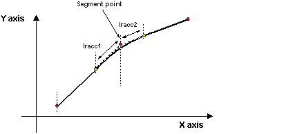
ParF1 = lracc1
ParF2 = lracc2
|
lracc1 is the length of the initial connection.
lracc2 is the length of the final connection.
lracc1 and lracc2, expressed in mm, determine the length of the interpolation zone.
If these lengths are too long (for example lracc1 > distance between the current point (Pn) and the previous point (Pn-1)), the maximum possible length should be used. This maximum length is automatically calculated by the module according to the previous section for lracc1 and the next section for lracc2.
Example: If the sum of lracc2 of Pn-1 and lracc1 of Pn is greater than the distance between Pn-1 and Pn, the linear part of the trajectory will resume at a reversal point on the trajectory between these two points. Hence the curve will be continuous, as will its differential coefficient.
In addition if lracc1 > lracc2/0.66 then interpolation considers that lracc1=lracc2/0.66
Similarly if lracc2 > lracc1/0.66 then interpolation considers that lracc2=lracc1/0.66
|
|
Code
|
Description
|
|---|---|
|
9501
|
One of the lengths lracc1 or lracc2 equals zero (illegal scenario).
|
|
9504
|
The table contains two consecutive identical points.
|
|
9514
|
Link too long: Next segment = 0
|
|
9515
|
The number of points in the linear segment is set to 0.
|
|
9516
|
The number of points in the 5º polynomial interpolation segment is set to 0.
|