|
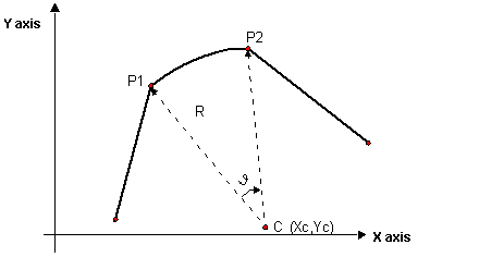
Circular Interpolation With Designated Center: Type 12
|
|
|
(Original Document)
|

|
Parameter
|
Description
|
|---|---|
|
ParW0
|
Enter 12 to indicate that the type of interpolation to be used is linear interpolation with circular interpolation connection for which the coordinates of the circle center are indicated.
|
|
ParW1 = NpLin
|
Indicate the number of points in the circle arc in this parameter. This number of points (minimum 1) represents the number of intermediate points that the module has to calculate in order to define the trajectory on this segment.
|
|
ParW4
|
Bit 0 at 0 for counter-clockwise trajectory direction.
Bit 0 at 1 for clockwise trajectory direction.
If a third tangent type axis is being used, select tangent mode (bit 8 of ParW4 at 1) to indicate that the motion of the third axis will follow the curve using tangent mode (positioning a tool for example so that it is always at right-angles to the curve and follows its tangent).
Note: Tangent mode (bit 8 at 1) will be available in a later version of the TjE/TSX CSY 85 combination, but for the moment only angular positioning of the third Z axis is supported.
|
|
ParF1 = Xc
ParF2 = Yc
|
Xc is the position of the center of the circle according to the X axis.
Yc is the position of the center of the circle according to the Y axis.
Note: The TSX CSY 85 module automatically recalculates the exact position of the center. However, if the position indicated differs from the exact position by more than half the length of the circle radius error code 9519 is generated.
|
|
Code
|
Description
|
|---|---|
|
9506
|
Use of circular type interpolation although more than two axes have been defined
|
|
9512
|
Circle impossible
|
|
9518
|
The number of points in the circular interpolation segment is set to 0.
|
|
9519
|
The designated center position is outside the tolerance limit permitted by the module.
|