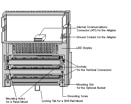
This section provides a drawing of a typical I/O base and describes basic features of I/O bases.
The front panel components of a typical I/O base are shown in the illustration below
Internal Communications Connector
The internal communications connector on an I/O base provides automatic communication to any adapter mounted on the base.
Each I/O base has a custom LED display, providing information about the status of input and output devices. Refer to the LED illustration and description for your I/O base for details.
This contact provides an earth ground connection to any adapter mounted on the base.
Terminal Connector Sockets
Each I/O base has sockets for as many as three terminal connectors. Terminal connectors are required for connecting I/O devices and must be ordered separately. For ordering information, see
Terminal Connectors.
A slot at the bottom of the I/O base allows a busbar to be attached to support 3- and 4-wire field devices. Busbars are optional. They must be ordered separately. For ordering information, see
Busbar Numbers.
Each I/O base has mounting holes for a panel mount and a locking tab for a DIN rail mount. For mounting instructions, see
Mounting TSX Momentum Devices.
TSX Momentum I/O bases are designed to meet CE mark requirements for open equipment. Other agency approvals can be found in the specifications for each I/O base module.
