Attaching a Busbar
Original instructions
Overview
This section describes how to attach a busbar to an I/O base.
General
An optional busbar may be inserted into the fourth row of an I/O base. Busbars provide a common connection for the field devices and serve as protective distribution connectors, for instance to PE. Each row of terminals on the busbar is connected internally. There is no connection to the I/O base.
NOTE: See the internal pin connections and field wiring diagrams associated with your I/O base to determine whether or not you need a busbar and which busbar best suits your needs.
Busbar Types
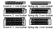
Depending on the I/O base and the type and number of field devices to which it is connected, a 1-, 2-, or 3-row busbar may be used. Busbars are separately ordered items; they are not shipped with the I/O bases. They are available in either screw-in and spring-clip versions.
Screw Size
For a screw-in type busbar, use the two, self-tapping Phillips head machine screws provided, to fasten it to the I/O base.
Busbar Numbers
The following table provides ordering information on the different busbar types:
Busbar Type
Part Number
# of Rows
Wire Size
Screw-in
170 XTS 006 01
1
One or two wires up to 10 AWG (4 mm2
170 XTS 005 01
2
One or two wires up to 14 AWG (1.5 mm2)
170 XTS 004 01
3
Spring-clip
170 XTS 007 01
1
170 XTS 008 01
2
170 XTS 003 01
3