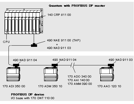
Example of a PROFIBUS DP Configuration
The following illustration shows an example configuration for the PROFIBUS DP. Only Momentum I/O modules are used:
NOTE: A PROFIBUS terminating connector (e.g. 490 NAD 911 03) must always be used at the front and back ends of the bus.
The following tasks must be executed to prepare a PROFIBUS DP network for operation:
NOTE: Analog Momentum I/O bases only attain data exchange status when a complete set of valid parameters together with the user data are transferred to them.
Installation of the Device Data Base File (GSD)
In PROFIBUS DP, the performance features of the devices are documented by the manufacturer and provided for the user in the form of an equipment data sheet and a device data base file (GSD) and are made available to the user. The contents and codification of the device data bases correspond to accepted standards, and are therefore independent of the master. They enable the configuration of any desired number of DP slaves using various manufacturers' configuration equipment.
The device data base file is delivered in the form of a diskette (file ASA_7512.GSD for Momentum modules) and is part of this user manual (see also
Ordering Details for PROFIBUS DP Components). A README file with further information is contained on this diskette. How to import this GSD file is described in Parameterizing the Master.
