|
Constructing the Bus Cable for the PROFIBUS DP
|
|
|
|
|
Step
|
Action
|
|---|---|
|
1
|
Cut the cable to the required length.
|
|
2
|
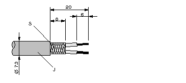
Prepare the cable ends as shown in the illustration (dimensions in mm):
 JPVC jacket SBraided shielding |
|
3
|
Remove the PVC jacket J to the length shown.
|
|
4
|
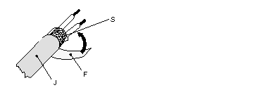
Wrap the supplied copper foil shielding F round the shielded braiding S:
 JPVC jacket SBraided shielding FCopper foil shielding Additional foil can be obtained from 3 M, see Ordering Details for PROFIBUS DP Components.
|
|
5
|
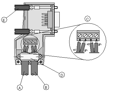
Plug the leads of the corresponding cable(s) into the terminals as shown:
Note: Do not screw the corresponding screws in yet.
Connection terminal assignment on the PROFIBUS DP (example: 490 NAD 911 04 PROFIBUS connector):
 AIncoming cable KAB PROFIB BOutgoing cable KAB PROFIB (not available with 490 NAD 911 03) CConnection terminals (only once (B,A) with 490 NAD 911 03) DCable cleat for relieving weight EBus connector screws |
|
6
|
Attach the cables with the available cable cleat to create a robust shielded connection and relieve weight as shown:
 JPVC jacket SBraided shielding with foil shielding CCable cleat Note: Half of the cable jacket must lie under the cable cleat.
Pay attention to the installation direction of the cable cleat.
|
|
7
|
The shielding of the two cables are each internally connected with the metal housing of the connector.
|
|
8
|
Close the connector housing.
|
|
9
|
Perform the central discharge function for the shielding in accordance with Central Discharge Function for the PROFIBUS DP, before connecting the bus cable to the modules.
|
|
10
|
Plug the PROFIBUS DP connector into the corresponding module and secure it with the screws.
|
