|
Indicators
|
|
|
Original instructions
|

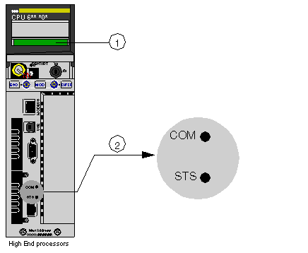
1LCD Display (lens cover closed)
2LED Indicators
|
LEDs
|
Indication
|
||
|---|---|---|---|
|
Standard Processors 140 CPU 65• •0 / 140 CPU 651 60S
|
Hot StandBy Processors 140 CPU 67• 6• / 140 CPU 671 60S
|
||
|
COM (yellow)
|
Controlled by the Coprocessor hardware
|
Controlled by the Coprocessor hardware
|
|
|
STS (yellow)
|
Controlled by the Coprocessor software
|
Controlled by the Coprocessor firmware
|
|
|
ON
|
Normal
|
||
|
OFF
|
Copro auto tests unsuccessful. Possible hardware problem.
|
||
|
Flashing:
|
|||
|
1 Flash
|
Configuration in progress.
Temporary situation.
|
||
|
2 Flashes
|
Invalid MAC address
|
||
|
3 Flashes
|
Link not connected
|
||
|
4 Flashes
|
Duplicate IP Address. Module is set to its default IP address.
|
||
|
5 Flashes
|
Waiting for IP address from address server
|
||
|
6 Flashes
|
Invalid IP address. Module is set to its default IP address.
|
||
|
7 Flashes
|
Firmware incompatibility between PLC OS and Copro firmware
|
||