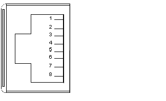
In front of the CPU the Modbus port is of type RJ45.
The network topology is determined by a protocol:
-
for RS-232, it’s a point to point topology,
-
for RS-485, it’s a bus topology with processor as master.
Connections on RJ45 are different, according to selected protocol. In configuration window of a 140 CPU 6•• •• Quantum PLC, the protocol is selected in tab Port Modbus.
Illustration:
The table following presents the pinouts of RS-232 and RS485 protocols:
|
Pin
|
RS-232 Signal
|
RS-485 Signal
|
|
1
|
DTR
|
D-
|
|
2
|
DSR
|
D+
|
|
3
|
TxD
|
|
|
4
|
RxD
|
Not used
|
|
5
|
GND
|
GND
|
|
6
|
RTS
|
|
|
7
|
CTS
|
Not used
|
|
8
|
GND (optional)
|
GND (optional)
|
NOTE: For RS-485 protocol pins 1 and 6 must be short circuited as well as pins 2 and 3.
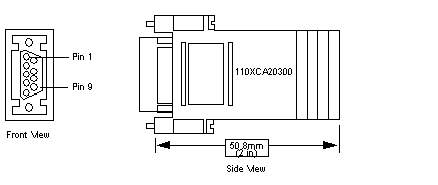
To connect PC-AT computers that have a 9-pin RS-232 port to the 8-pin RJ45 Modbus port on the 140 CPU 651 •0, 140 CPU 670 60, 140 CPU 671 60, 140 CPU 672 60 and 140 CPU 672 61, you must connect the 110 XCA 020 300 adapter (9-pin/RJ45) on the PC with the straight 110 XCA 28 202 cable (8-pin RJ45 to 8-pin RJ45).
The following figures show the 9-pin adapter front view (left) and side view (right).
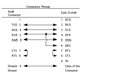
The following figure shows the 9-pin RJ45 connector schematic.


