|
|
Original instructions
|
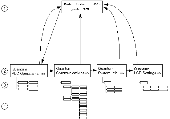
1default screen
2system menus
3sub menus
4sub screens
|
Step
|
Action
|
|---|---|
|
1
|
 |
|
2
|
To step down to a lower menu, operate one of the following keys:
 |
|
3
|
To return to the previous menu, press:
 |

|
Field
|
Display
|
Description
|
|
|---|---|---|---|
|
0
|
CPU mode
|
M
|
maintenance mode (only on safety processors)
|
|
S
|
safe mode (only on safety processors)
|
||
|
2
|
CPU state
|
RUN
|
Application program is running.
|
|
STOP
|
Application program is NOT running.
|
||
|
STOP offline
|
|||
|
No Conf
|
Processor has no application program.
|
||
|
Halt
|
detected state error (in maintenance mode for safety modules)
|
||
|
BatL
|
Indicates battery health:
|
||
|
Port
|
USB
|
Indicates that the port has activity.
|
|
|
Modbus Plus
|
MB+
|
Indicates Modbus Plus activity.
|
|
|
mb+
|
no activity
|
||
|
Dup
|
duplicate MB+ address
|
||
|
ERR
|
detected Modbus communications error
|
||
|
INI
|
initial network search
|
||
|
Modbus
|
232
|
serial port activity for RS-232
|
|
|
485
|
serial port activity for RS-485
|
||
|
PCM
|
1
|
Displayed status indicates battery health of the PCMCIA card in slot 1:
|
|
|
2
|
Displayed status indicates battery health of the PCMCIA card in slot 2:
|
||
| (1) With blue PCMCIAs (version >= 04), when main battery is low, there is no flash. | |||
|
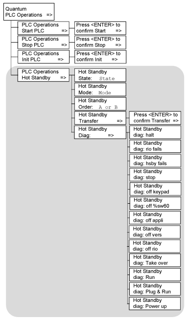
Start, Stop, Init Screens Display
|
Fields Available
|
Description
|
||
|---|---|---|---|---|
|
Start PLC
|
Press <ENTER> to confirm Start.
|
Pressing <ENTER> starts the controller.
|
||
|
Stop PLC
|
Press <ENTER> to confirm Stop.
|
Pressing <ENTER> stops the controller.
|
||
|
Init PLC
|
Press <ENTER> to confirm Init.
|
Pressing <ENTER> initializes the controller.
On safety processors, this command is only available in the maintenance mode.
|
||
|
Screen
|
Field
|
Option
|
Description
|
|
|---|---|---|---|---|
|
Hot Standby State:
|
State
read-only
|
PRIMARY CPU
|
Controller serves as primary unit.
|
|
|
STANDBY CPU
|
Controller serves as standby unit.
|
|||
|
Offline
|
Controller is neither primary nor standby unit.
|
|||
|
Hot Standby Mode:
|
Mode
(modifiable only if the key switch is in the unlocked position)
|
RUN
|
STS steady
|
Controller is active and is either serving as primary PLC or able to take over the primary PLC role if needed.
|
|
STS flashing
|
Controller is transferring/updating. When the transfer is done, RUN stays on steady.
|
|||
|
OFFLINE
|
STS steady
|
Controller is taken out of service without stopping it or disconnecting it from power.
If the controller is the primary PLC when the mode is changed to offline, control switches to the standby PLC.
If the standby PLC changes to offline, the primary PLC continues to operate without a backup.
|
||
|
STS flashing
|
Controller is transferring/updating.When the transfer is done, OFFLINE stays on steady.
|
|||
|
Hot Standby Order:
|
A or B
(modifiable only if the key switch is in the unlocked position)
|
FIRST
|
Hot Standby power order
NOTE: To change the A/B order, confirm that the PLC is in STOP mode. |
|
|
SECOND
|
||||
|
Hot Standby Transfer:
|
-
(This menu option is enabled only when the key switch is in the unlocked position.)
|
Pressing the <ENTER> key confirms the transfer. The transfer initiates the request of a program update from the primary PLC. Pressing any other key cancels the transfer initiation and returns to the Hot Standby Transfer menu option screen.
NOTE: Transfer by keypad is based on %SW60.5 use: modifying %SW60.5 by application and requiring simultaneously a transfer by Keypad, could lead to some issues (no transfer or transfer retry). |
||
|
Hot Standby Diag:
|
The order of diagnostic screen varies with the operation.
|
|||
|
Halt
|
user task in halt mode
|
|||
|
RIO fails
|
detected error reported by RIO head
|
|||
|
HSBY fails
|
detected error reported by optical link
|
|||
|
Stop
|
stop command sent
|
|||
|
Off keypad
|
offline command entered on keypad
|
|||
|
Off %SW60
|
offline command set in command register
|
|||
|
Off appli
|
offline due to application mismatch
|
|||
|
Off vers
|
offline due to PLC or co-processor OS mismatch
|
|||
|
Off RIO
|
offline due to detectedRIO error
|
|||
|
Take over
|
standby CPU switched to primary CPU mode
|
|||
|
Run
|
run command sent
|
|||
|
Plug & Run
|
sun-link operational and standby CPU started
|
|||
|
Power up
|
no message: PLC just started
|
|||
|
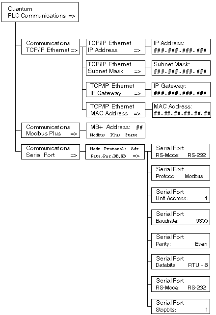
TCP/IP Ethernet Screen Displays
|
Fields Available
|
Options Available
|
Description
|
|
|---|---|---|---|---|
|
TCP/IP Ethernet IP Address1,2
|
###.###.###.###
|
decimal numbers
|
Displays IP address.
|
|
|
TCP/IP Ethernet Subnet Mask1,2
|
###.###.###.###
|
decimal numbers
|
Displays subnetwork mask address.
|
|
|
TCP/IP Ethernet IP Gateway1,2
|
###.###.###.###
|
decimal numbers
|
Displays Ethernet IP gateway address.
|
|
|
TCP/IP Ethernet MAC Address
|
##.##.##.##.##.##
(read-only)
|
hexadecimal numbers
|
Displays MAC address.
|
|
|
Fields Available
|
Options Available
|
Description
|
|
|---|---|---|---|
|
##
(modifiable only if the key switch is in the unlocked position)
|
1-64
|
Enter a valid Modbus Plus address.
|
|
|
Modbus Plus State
|
Monitor Link
|
Modbus Plus state
|
|
|
Normal Link
|
|||
|
Sole Station
|
|||
|
Duplicate Address
|
|||
|
No Token
|
|||
|
Fields Available*
|
Options Available
|
Description
|
|
|---|---|---|---|
|
Mode
|
232
|
RS mode
|
|
|
485
|
|||
|
Protocol
|
ASCII
|
protocols available
|
|
|
RTU
|
|||
|
Adr
|
1 - 247
|
unit address
|
|
|
for Modbus Switchover
Primary CPU 1-119
Standby CPU 129 - 247
|
|||
|
Rate
|
50, 75, 110, 134.5, 150, 300, 600, 1200, 1800, 2400, 3600. 4800, 7200, 9600, 19200 bits/s
|
baud rate
|
|
|
Par
|
NONE
|
parity
|
|
|
ODD
|
|||
|
EVEN
|
|||
|
DB
|
7,8
|
data bits: If protocol is Modbus, then RTU-8 or ASCII-7.
|
|
|
SB
|
1,2
|
stop bits
|
|
|
*If the key switch is in the unlocked position, fields are modifiable.
|
|||
|
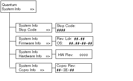
System Info Screen Displays
|
Fields Available*
|
Option Available
|
Description
|
|
|---|---|---|---|---|
|
Stop Code
|
####
|
machine stop code
|
||
|
Description
|
description of the machine stop code
|
|||
|
Firmware Info
|
Rev.Ldr: ##.##
|
OS revision
|
||
|
OS: ##.##-##-##
|
OSLoader revision
|
|||
|
Hardware Info
|
HW Rev: ####
|
hardware revision
|
||
|
Copro Info
|
##-IE-##
|
co-processor revision
|
||
|
*Fields are read-only.
|
||||
|
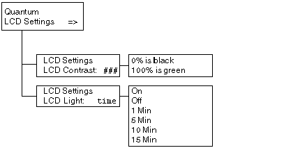
LCD Screen Contrast Screen Displays
|
Fields Available
|
Description
|
|---|---|---|
|
LCD Contrast:
|
####
|
Use the arrow keys to adjust the setting:
|
|
Screen Displays
|
Fields Available
|
Description
|
|---|---|---|
|
LCD Light:
|
On
|
LCD remains on permanently or until changed.
|
|
Off
|
LCD remains off permanently or until changed.
|
|
|
1 Min
|
LCD remains on for 1 minute.
|
|
|
5 Min
|
LCD remains on for 5 minutes.
|
|
|
10 Min
|
LCD remains on for 10 minutes.
|
|
|
15 Min
|
LCD remains on for 15 minutes.
|