I/O Configuration for Discrete Output Modules
Original instructions
Overview
This section provides information on configuration of 8-, 12-, 16-, 32- and 96-point output modules.
8-Point Output Modules
The following shows the 8-point output module:
Flat Addressing
The ouput modules listed above can be configured as either eight contiguous discrete %M output references or as one %MW output word. For a description of how to access the input points, please refer to Discrete I/O Bit Numbering.
Topological Addressing
The following tables show the topological addresses for the 8-Point Output Modules.
Topological addresses in Bit Mapping format:
Point
I/O Object
Comment
Output 1
%Q[\b.e\]r.m.1
Value
Output 2
%Q[\b.e\]r.m.2
Value
• • •
Output 7
%Q[\b.e\]r.m.7
Value
Output 8
%Q[\b.e\]r.m.8
Value
Topological addresses in Word Mapping format:
Point
I/O Object
Comment
Outputword 1
%QW[\b.e\]R.S.1.1
Value
Used abbreviations: b = bus, e = equipment (drop), r = rack, m = module slot.
I/O Map Status Byte
There is no I/O Map status byte associated with these modules.
12-Point Output Module
The 12-point output module is:
Flat Addressing (Error Inputs)
The Error Inputs of the 140 DDO 885 00 can be configured as either 16 contiguous %I references or as one %IW word. For a description of how to access the input points, please refer to Discrete I/O Bit Numbering.
Topological Addressing
The following tables show the topological addresses for the 12-Point Error Inputs.
Topological addresses in Bit Mapping format:
Point
I/O Object
Comment
Input 1
%I[\b.e\]r.m.1
Value
Input 2
%I[\b.e\]r.m.2
Value
• • •
Input 11
%I[\b.e\]r.m.11
Value
Input 12
%I[\b.e\]r.m.12
Value
Topological addresses in Word Mapping format:
Point
I/O Object
Comment
Inputword 1
%IW[\b.e\]r.m.1.1
Value
Used abbreviations: b = bus, e = equipment (drop), r = rack, m = module slot.
Flat Addressing (Outputs)
The 140DDO88500 can be configured as one %MW output word in the following format. For a description of how to access the input points, please refer to Discrete I/O Bit Numbering.
Topological Addressing
The following tables show the topological addresses for the 12-Point Output Modules.
Topological addresses in Bit Mapping format:
Point
I/O Object
Comment
Output 1
%Q[\b.e\]r.m.1
Value
Output 2
%Q[\b.e\]r.m.2
Value
• • •
Output 11
%Q[\b.e\]r.m.11
Value
Output 12
%Q[\b.e\]r.m.12
Value
Topological addresses in Word Mapping format:
Point
I/O Object
Comment
Outputword 1
%QW[\b.e\]r.m.1.1
Value
Used abbreviations: b = bus, e = equipment (drop), r = rack, m = module slot.
I/O Map Status Byte (Outputs)
The least significant bit in the output I/O map status byte is used as follows. For a description of how to access the input points, please refer to Discrete I/O Bit Numbering.
16-Point Output Modules
The 16-point output modules are as follows:
Flat Addressing
The output modules listed above can be configured as either 16 contiguous discrete %M output references, or as one %MW output word in the following formats. For a description of how to access the input points, please refer to Discrete I/O Bit Numbering.
Topological Addressing
The following tables show the topological addresses for the 16-Point Output Modules.
Topological addresses in Bit Mapping format:
Point
I/O Object
Comment
Output 1
%Q[\b.e\]r.m.1
Value
Output 2
%Q[\b.e\]r.m.2
Value
• • •
Output 15
%Q[\b.e\]r.m.15
Value
Output 16
%Q[\b.e\]r.m.16
Value
Topological addresses in Word Mapping format:
Point
I/O Object
Comment
Outputword 1
%QW[\b.e\]r.m.1.1
Value
Used abbreviations: b = bus, e = equipment (drop), r = rack, m = module slot.
I/O Map Status Byte
The I/O map status byte is used by the 140DAO84210 and 140DAO84220 output modules. The following figure shows I/O map status bytes use.
There is no I/O map status byte associated with the 140DAO84000, 140DAO84010, 140DDO84300, or 140DRA84000 module.
32-Point Output Modules
The following list shows the 32-point output modules:
For addressing information of the 140DVO85300, please refer to Addressing.
Flat Addressing
The output modules listed above can be configured as either 32 contiguous %M references, or as two %MW words in the following format. For a description of how to access the input points, please refer to Discrete I/O Bit Numbering.
Topological Addressing
The following tables show the topological addresses for the 32-Point Output Modules.
Topological addresses in Bit Mapping format:
Point
I/O Object
Comment
Output 1
%Q[\b.e\]r.m.1
Value
Output 2
%Q[\b.e\]r.m.2
Value
• • •
Output 31
%Q[\b.e\]r.m.31
Value
Output 32
%Q[\b.e\]r.m.32
Value
Topological addresses in Word Mapping format:
Point
I/O Object
Comment
Outputword 1
%QW[\b.e\]r.m.1.1
Value
Outputword 2
%QW[\b.e\]r.m.1.2
Value
Used abbreviations: b = bus, e = equipment (drop), r = rack, m = module slot.
I/O Map Status Byte
The I/O map status byte is used by the modules as follows:
96-Point Output Module
The 96 point output module is:
Flat Addressing
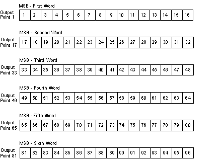
The following figures show the words 1 through 6 format for the 140DDO36400 output module. For a description of how to access the input points, please refer to Discrete I/O Bit Numbering.
Topological Addressing
The following tables show the topological addresses for the 16-Point Output Modules.
Topological addresses in Bit Mapping format:
Point
I/O Object
Comment
Output 1
%Q[\b.e\]r.m.1
Value
Output 2
%Q[\b.e\]r.m.2
Value
• • •
Output 95
%Q[\b.e\]r.m.95
Value
Output 96
%Q[\b.e\]r.m.96
Value
Topological addresses in Word Mapping format:
Point
I/O Object
Comment
Outputword 1
%QW[\b.e\]r.m.1.1
Value
Outputword 2
%QW[\b.e\]r.m.1.2
Value
Outputword 3
%QW[\b.e\]r.m.1.3
Value
Outputword 4
%QW[\b.e\]r.m.1.4
Value
Outputword 5
%QW[\b.e\]r.m.1.5
Value
Outputword 6
%QW[\b.e\]r.m.1.6
Value
Used abbreviations: b = bus, e = equipment (drop), r = rack, m = module slot.
I/O Map Status Byte
The I/O map status byte is used by the module as follows: