I/O Configuration for Discrete Input/Output Modules
Original instructions
Overview
This section provides information on configuration of 4 In/4 Out and 16 In/8 Out modules.
4-Point Input/4-Point Output Module
The following shows the 4 In/4 Out module:
Flat Addressing
The 140DDM69000 input/output module can be configured as either eight contiguous %I references; or as one %IW word and either eight contiguous %M references or one %MW word.
CAUTION
UNINTENDED EQUIPMENT OPERATION - INCORRECT I/O MAPPING
When I/O mapping module inputs using discrete %I references in remote drops, do not split discrete words between drops. The lowest discrete reference for a drop should start on a word boundary.
Failure to follow these instructions can result in injury or equipment damage.
I/O Map Register (Inputs)
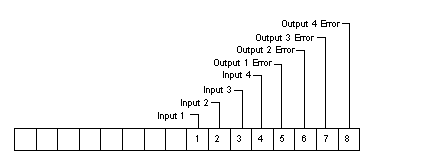
The following figure shows the %IW input word.
I/O Map Assignment (Outputs)
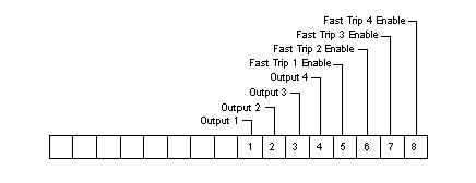
The following figure shows the %MW output word.
In Fast Trip Mode, each output can be turned ON by the Command Bit (e.g., Output 1) or by the corresponding Input Bit plus the Fast Trip Enable Bit (e.g., last order Input 1 controls Output 1 directly).
Topological Addressing
The following tables show the topological addressing for the 140 DDM 690 00 Input/Output Module.
Topological addresses in Bit Mapping format:
Point
I/O Object
Comment
Input 1
%I[\b.e\]r.m.1
Value
Input 2
%I[\b.e\]r.m.2
Value
• • •
Input 7
%I[\b.e\]r.m.7
Value
Input 8
%I[\b.e\]r.m.8
Value
Output 1
%Q[\b.e\]r.m.1
Value
Output 2
%Q[\b.e\]r.m.2
Value
• • •
Output 7
%Q[\b.e\]r.m.7
Value
Output 8
%Q[\b.e\]r.m.8
Value
Topological addresses in Word Mapping format:
Point
I/O Object
Comment
Inputword 1
%IW[\b.e\]r.m.1.1
Value
Outputword 1
%QW[\b.e\]r.m.1.1
Value
Used abbreviations: b = bus, e = equipment (drop), r = rack, m = module slot.
I/O Map Status Byte (Outputs)
The four least significant bits in the I/O map status are used as follows:
16-Point Input/8-Point Output Modules
The following information pertains to the 140 DAM 590 00 (AC Input 115 Vac 2x8 / AC Output 115 Vac 2x4) and the 140 DDM 390 00 (DC Input 24 Vdc 2x8 / DC Output 24 Vdc 2x4) modules.
Flat Addressing
The modules listed above can be configured as either 16 contiguous %I references or as one %IW word and as one %MW word.
I/O Map Register (Inputs)
The following figure shows the %IW input word. For a description of how to access the input points, please refer to Discrete I/O Bit Numbering.
I/O Map Assignment (Outputs)
The modules listed above can be configured as 8 %M references or as 1 %MW output word in the following format. For a description of how to access the input points, please refer to Discrete I/O Bit Numbering.
Topological Addressing
The following tables show the topological addresses for the 16/8-Point Input/Output Modules.
Topological addresses in Bit Mapping format:
Point
I/O Object
Comment
Input 1
%I[\b.e\]r.m.1
Value
Input 2
%I[\b.e\]r.m.2
Value
• • •
Input 15
%I[\b.e\]r.m.15
Value
Input 16
%I[\b.e\]r.m.16
Value
Output 1
%Q[\b.e\]r.m.1
Value
Output 2
%Q[\b.e\]r.m.2
Value
• • •
Output 7
%Q[\b.e\]r.m.7
Value
Output 8
%Q[\b.e\]r.m.8
Value
Topological addresses in Word Mapping format:
Point
I/O Object
Comment
Inputword 1
%IW[\b.e\]r.m.1.1
Value
Outputword 1
%QW[\b.e\]r.m.1.1
Value
Used abbreviations: b = bus, e = equipment (drop), r = rack, m = module slot.
I/O Map Status Byte (Outputs)
The two least significant bits in the output I/O map status byte are used as follows.